7-24 750/760 Feeder Management Relay GE Multilin
7.4 MODBUS MEMORY MAP 7 COMMUNICATIONS
7
12A3
8
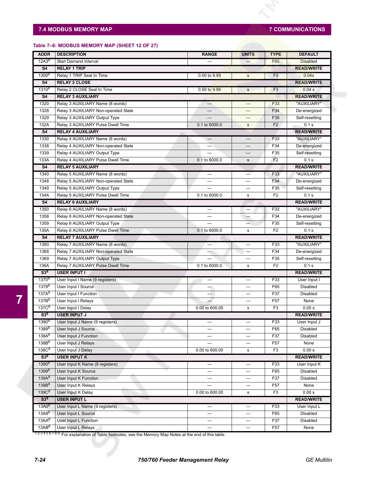
Start Demand Interval --- --- F65 Disabled
S4 RELAY 1 TRIP READ/WRITE
1300
8
Relay 1 TRIP Seal In Time 0.00 to 9.99 s F3 0.04s
S4 RELAY 2 CLOSE READ/WRITE
1310
8
Relay 2 CLOSE Seal In Time 0.00 to 9.99 s F3 0.04 s
S4 RELAY 3 AUXILIARY READ/WRITE
1320 Relay 3 AUXILIARY Name (8 words) --- --- F33 "AUXILIARY"
1328 Relay 3 AUXILIARY Non-operated State --- --- F34 De-energized
1329 Relay 3 AUXILIARY Output Type --- --- F35 Self-resetting
132A Relay 3 AUXILIARY Pulse Dwell Time 0.1 to 6000.0 s F2 0.1 s
S4 RELAY 4 AUXILIARY READ/WRITE
1330 Relay 4 AUXILIARY Name (8 words) --- --- F33 "AUXILIARY"
1338 Relay 4 AUXILIARY Non-operated State --- --- F34 De-energized
1339 Relay 4 AUXILIARY Output Type --- --- F35 Self-resetting
133A Relay 4 AUXILIARY Pulse Dwell Time 0.1 to 6000.0 s F2 0.1 s
S4 RELAY 5 AUXILIARY READ/WRITE
1340 Relay 5 AUXILIARY Name (8 words) --- --- F33 "AUXILIARY"
1348 Relay 5 AUXILIARY Non-operated State --- --- F34 De-energized
1349 Relay 5 AUXILIARY Output Type --- --- F35 Self-resetting
134A Relay 5 AUXILIARY Pulse Dwell Time 0.1 to 6000.0 s F2 0.1 s
S4 RELAY 6 AUXILIARY READ/WRITE
1350 Relay 6 AUXILIARY Name (8 words) --- --- F33 "AUXILIARY"
1358 Relay 6 AUXILIARY Non-operated State --- --- F34 De-energized
1359 Relay 6 AUXILIARY Output Type --- --- F35 Self-resetting
135A Relay 6 AUXILIARY Pulse Dwell Time 0.1 to 6000.0 s F2 0.1 s
S4 RELAY 7 AUXILIARY READ/WRITE
1360 Relay 7 AUXILIARY Name (8 words) --- --- F33 "AUXILIARY"
1368 Relay 7 AUXILIARY Non-operated State --- --- F34 De-energized
1369 Relay 7 AUXILIARY Output Type --- --- F35 Self-resetting
136A Relay 7 AUXILIARY Pulse Dwell Time 0.1 to 6000.0 s F2 0.1 s
S3
8
USER INPUT I READ/WRITE
1370
8
User Input I Name (9 registers) --- --- F33 User Input I
1379
8
User Input I Source --- --- F65 Disabled
137A
8
User Input I Function --- --- F37 Disabled
137B
8
User Input I Relays --- --- F57 None
137C
8
User Input I Delay 0.00 to 600.00 s F3 0.00 s
S3
8
USER INPUT J READ/WRITE
1380
8
User Input J Name (9 registers) --- --- F33 User Input J
1389
8
User Input J Source --- --- F65 Disabled
138A
8
User Input J Function --- --- F37 Disabled
138B
8
User Input J Relays --- --- F57 None
138C
8
User Input J Delay 0.00 to 600.00 s F3 0.00 s
S3
8
USER INPUT K READ/WRITE
1390
8
User Input K Name (9 registers) --- --- F33 User Input K
1399
8
User Input K Source --- --- F65 Disabled
139A
8
User Input K Function --- --- F37 Disabled
139B
8
User Input K Relays --- --- F57 None
139C
8
User Input K Delay 0.00 to 600.00 s F3 0.00 s
S3
8
USER INPUT L READ/WRITE
13A0
8
User Input L Name (9 registers) --- --- F33 User Input L
13A9
8
User Input L Source --- --- F65 Disabled
13AA
8
User Input L Function --- --- F37 Disabled
13AB
8
User Input L Relays --- --- F57 None
Table 7–6: MODBUS MEMORY MAP (SHEET 12 OF 27)
ADDR DESCRIPTION RANGE UNITS TYPE DEFAULT
1 2 3 4 5 6 7 8 9
For explanation of Table footnotes, see the Memory Map Notes at the end of this table.
Courtesy of NationalSwitchgear.com
 Loading...


