7-28 750/760 Feeder Management Relay GE Multilin
7.4 MODBUS MEMORY MAP 7 COMMUNICATIONS
7
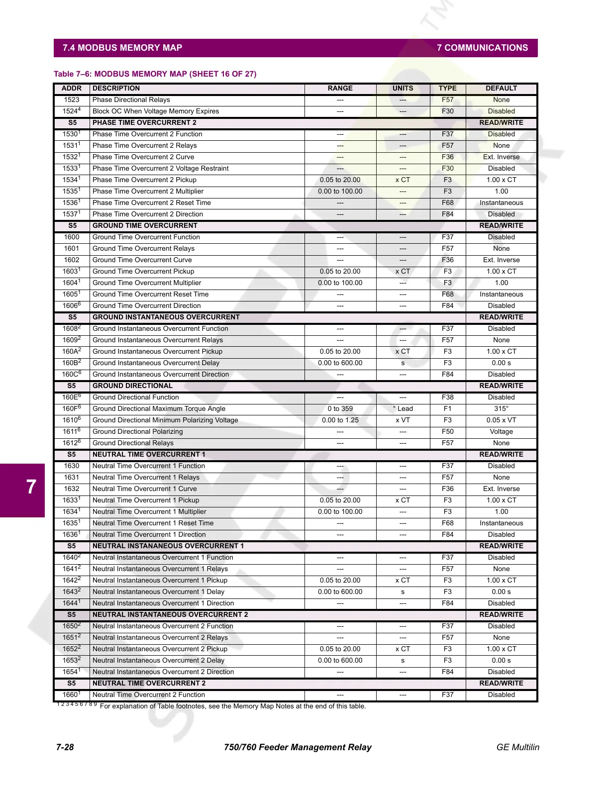
1523 Phase Directional Relays --- --- F57 None
1524
4
Block OC When Voltage Memory Expires --- --- F30 Disabled
S5 PHASE TIME OVERCURRENT 2 READ/WRITE
1530
1
Phase Time Overcurrent 2 Function --- --- F37 Disabled
1531
1
Phase Time Overcurrent 2 Relays --- --- F57 None
1532
1
Phase Time Overcurrent 2 Curve --- --- F36 Ext. Inverse
1533
1
Phase Time Overcurrent 2 Voltage Restraint --- --- F30 Disabled
1534
1
Phase Time Overcurrent 2 Pickup 0.05 to 20.00 x CT F3 1.00 x CT
1535
1
Phase Time Overcurrent 2 Multiplier 0.00 to 100.00 --- F3 1.00
1536
1
Phase Time Overcurrent 2 Reset Time --- --- F68 Instantaneous
1537
1
Phase Time Overcurrent 2 Direction --- --- F84 Disabled
S5 GROUND TIME OVERCURRENT READ/WRITE
1600 Ground Time Overcurrent Function --- --- F37 Disabled
1601 Ground Time Overcurrent Relays --- --- F57 None
1602 Ground Time Overcurrent Curve --- --- F36 Ext. Inverse
1603
1
Ground Time Overcurrent Pickup 0.05 to 20.00 x CT F3 1.00 x CT
1604
1
Ground Time Overcurrent Multiplier 0.00 to 100.00 --- F3 1.00
1605
1
Ground Time Overcurrent Reset Time --- --- F68 Instantaneous
1606
6
Ground Time Overcurrent Direction --- --- F84 Disabled
S5 GROUND INSTANTANEOUS OVERCURRENT READ/WRITE
1608
2
Ground Instantaneous Overcurrent Function --- --- F37 Disabled
1609
2
Ground Instantaneous Overcurrent Relays --- --- F57 None
160A
2
Ground Instantaneous Overcurrent Pickup 0.05 to 20.00 x CT F3 1.00 x CT
160B
2
Ground Instantaneous Overcurrent Delay 0.00 to 600.00 s F3 0.00 s
160C
6
Ground Instantaneous Overcurrent Direction --- --- F84 Disabled
S5 GROUND DIRECTIONAL READ/WRITE
160E
6
Ground Directional Function --- --- F38 Disabled
160F
6
Ground Directional Maximum Torque Angle 0 to 359 ° Lead F1 315°
1610
6
Ground Directional Minimum Polarizing Voltage 0.00 to 1.25 x VT F3 0.05 x VT
1611
6
Ground Directional Polarizing --- --- F50 Voltage
1612
6
Ground Directional Relays --- --- F57 None
S5 NEUTRAL TIME OVERCURRENT 1 READ/WRITE
1630 Neutral Time Overcurrent 1 Function --- --- F37 Disabled
1631 Neutral Time Overcurrent 1 Relays --- --- F57 None
1632 Neutral Time Overcurrent 1 Curve --- --- F36 Ext. Inverse
1633
1
Neutral Time Overcurrent 1 Pickup 0.05 to 20.00 x CT F3 1.00 x CT
1634
1
Neutral Time Overcurrent 1 Multiplier 0.00 to 100.00 --- F3 1.00
1635
1
Neutral Time Overcurrent 1 Reset Time --- --- F68 Instantaneous
1636
1
Neutral Time Overcurrent 1 Direction --- --- F84 Disabled
S5 NEUTRAL INSTANANEOUS OVERCURRENT 1 READ/WRITE
1640
2
Neutral Instantaneous Overcurrent 1 Function --- --- F37 Disabled
1641
2
Neutral Instantaneous Overcurrent 1 Relays --- --- F57 None
1642
2
Neutral Instantaneous Overcurrent 1 Pickup 0.05 to 20.00 x CT F3 1.00 x CT
1643
2
Neutral Instantaneous Overcurrent 1 Delay 0.00 to 600.00 s F3 0.00 s
1644
1
Neutral Instantaneous Overcurrent 1 Direction --- --- F84 Disabled
S5 NEUTRAL INSTANTANEOUS OVERCURRENT 2 READ/WRITE
1650
2
Neutral Instantaneous Overcurrent 2 Function --- --- F37 Disabled
1651
2
Neutral Instantaneous Overcurrent 2 Relays --- --- F57 None
1652
2
Neutral Instantaneous Overcurrent 2 Pickup 0.05 to 20.00 x CT F3 1.00 x CT
1653
2
Neutral Instantaneous Overcurrent 2 Delay 0.00 to 600.00 s F3 0.00 s
1654
1
Neutral Instantaneous Overcurrent 2 Direction --- --- F84 Disabled
S5 NEUTRAL TIME OVERCURRENT 2 READ/WRITE
1660
1
Neutral Time Overcurrent 2 Function --- --- F37 Disabled
Table 7–6: MODBUS MEMORY MAP (SHEET 16 OF 27)
ADDR DESCRIPTION RANGE UNITS TYPE DEFAULT
1 2 3 4 5 6 7 8 9
For explanation of Table footnotes, see the Memory Map Notes at the end of this table.
Courtesy of NationalSwitchgear.com
 Loading...


