7-36 750/760 Feeder Management Relay GE Multilin
7.4 MODBUS MEMORY MAP 7 COMMUNICATIONS
7
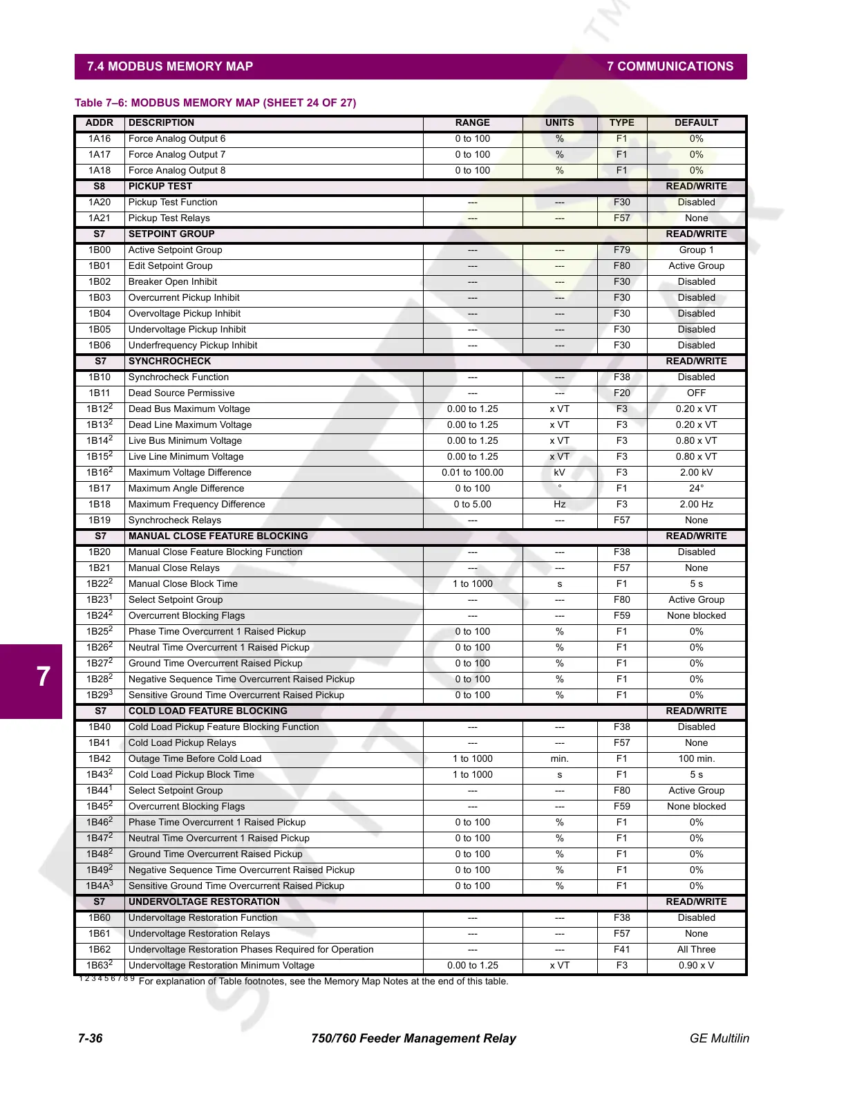
1A16 Force Analog Output 6 0 to 100 % F1 0%
1A17 Force Analog Output 7 0 to 100 % F1 0%
1A18 Force Analog Output 8 0 to 100 % F1 0%
S8 PICKUP TEST READ/WRITE
1A20 Pickup Test Function --- --- F30 Disabled
1A21 Pickup Test Relays --- --- F57 None
S7 SETPOINT GROUP READ/WRITE
1B00 Active Setpoint Group --- --- F79 Group 1
1B01 Edit Setpoint Group --- --- F80 Active Group
1B02 Breaker Open Inhibit --- --- F30 Disabled
1B03 Overcurrent Pickup Inhibit --- --- F30 Disabled
1B04 Overvoltage Pickup Inhibit --- --- F30 Disabled
1B05 Undervoltage Pickup Inhibit --- --- F30 Disabled
1B06 Underfrequency Pickup Inhibit --- --- F30 Disabled
S7 SYNCHROCHECK READ/WRITE
1B10 Synchrocheck Function --- --- F38 Disabled
1B11 Dead Source Permissive --- --- F20 OFF
1B12
2
Dead Bus Maximum Voltage 0.00 to 1.25 x VT F3 0.20 x VT
1B13
2
Dead Line Maximum Voltage 0.00 to 1.25 x VT F3 0.20 x VT
1B14
2
Live Bus Minimum Voltage 0.00 to 1.25 x VT F3 0.80 x VT
1B15
2
Live Line Minimum Voltage 0.00 to 1.25 x VT F3 0.80 x VT
1B16
2
Maximum Voltage Difference 0.01 to 100.00 kV F3 2.00 kV
1B17 Maximum Angle Difference 0 to 100 ° F1 24°
1B18 Maximum Frequency Difference 0 to 5.00 Hz F3 2.00 Hz
1B19 Synchrocheck Relays --- --- F57 None
S7 MANUAL CLOSE FEATURE BLOCKING READ/WRITE
1B20 Manual Close Feature Blocking Function --- --- F38 Disabled
1B21 Manual Close Relays --- --- F57 None
1B22
2
Manual Close Block Time 1 to 1000 s F1 5 s
1B23
1
Select Setpoint Group --- --- F80 Active Group
1B24
2
Overcurrent Blocking Flags --- --- F59 None blocked
1B25
2
Phase Time Overcurrent 1 Raised Pickup 0 to 100 % F1 0%
1B26
2
Neutral Time Overcurrent 1 Raised Pickup 0 to 100 % F1 0%
1B27
2
Ground Time Overcurrent Raised Pickup 0 to 100 % F1 0%
1B28
2
Negative Sequence Time Overcurrent Raised Pickup 0 to 100 % F1 0%
1B29
3
Sensitive Ground Time Overcurrent Raised Pickup 0 to 100 % F1 0%
S7 COLD LOAD FEATURE BLOCKING READ/WRITE
1B40 Cold Load Pickup Feature Blocking Function --- --- F38 Disabled
1B41 Cold Load Pickup Relays --- --- F57 None
1B42 Outage Time Before Cold Load 1 to 1000 min. F1 100 min.
1B43
2
Cold Load Pickup Block Time 1 to 1000 s F1 5 s
1B44
1
Select Setpoint Group --- --- F80 Active Group
1B45
2
Overcurrent Blocking Flags --- --- F59 None blocked
1B46
2
Phase Time Overcurrent 1 Raised Pickup 0 to 100 % F1 0%
1B47
2
Neutral Time Overcurrent 1 Raised Pickup 0 to 100 % F1 0%
1B48
2
Ground Time Overcurrent Raised Pickup 0 to 100 % F1 0%
1B49
2
Negative Sequence Time Overcurrent Raised Pickup 0 to 100 % F1 0%
1B4A
3
Sensitive Ground Time Overcurrent Raised Pickup 0 to 100 % F1 0%
S7 UNDERVOLTAGE RESTORATION READ/WRITE
1B60 Undervoltage Restoration Function --- --- F38 Disabled
1B61 Undervoltage Restoration Relays --- --- F57 None
1B62 Undervoltage Restoration Phases Required for Operation --- --- F41 All Three
1B63
2
Undervoltage Restoration Minimum Voltage 0.00 to 1.25 x VT F3 0.90 x V
Table 7–6: MODBUS MEMORY MAP (SHEET 24 OF 27)
ADDR DESCRIPTION RANGE UNITS TYPE DEFAULT
1 2 3 4 5 6 7 8 9
For explanation of Table footnotes, see the Memory Map Notes at the end of this table.
Courtesy of NationalSwitchgear.com
 Loading...


