GE Multilin 750/760 Feeder Management Relay 7-35
7 COMMUNICATIONS 7.4 MODBUS MEMORY MAP
7
1953
3
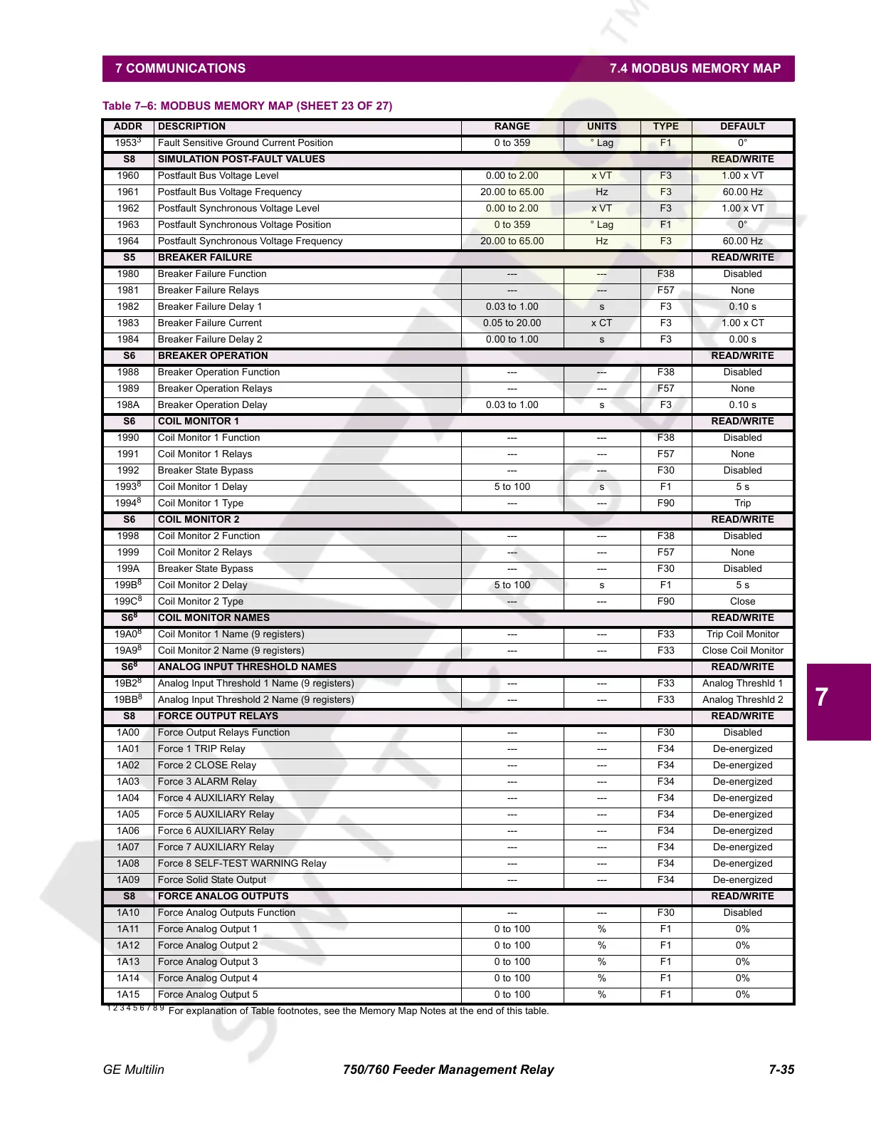
Fault Sensitive Ground Current Position 0 to 359 ° Lag F1 0°
S8 SIMULATION POST-FAULT VALUES READ/WRITE
1960 Postfault Bus Voltage Level 0.00 to 2.00 x VT F3 1.00 x VT
1961 Postfault Bus Voltage Frequency 20.00 to 65.00 Hz F3 60.00 Hz
1962 Postfault Synchronous Voltage Level 0.00 to 2.00 x VT F3 1.00 x VT
1963 Postfault Synchronous Voltage Position 0 to 359 ° Lag F1 0°
1964 Postfault Synchronous Voltage Frequency 20.00 to 65.00 Hz F3 60.00 Hz
S5 BREAKER FAILURE READ/WRITE
1980 Breaker Failure Function --- --- F38 Disabled
1981 Breaker Failure Relays --- --- F57 None
1982 Breaker Failure Delay 1 0.03 to 1.00 s F3 0.10 s
1983 Breaker Failure Current 0.05 to 20.00 x CT F3 1.00 x CT
1984 Breaker Failure Delay 2 0.00 to 1.00 s F3 0.00 s
S6 BREAKER OPERATION READ/WRITE
1988 Breaker Operation Function --- --- F38 Disabled
1989 Breaker Operation Relays --- --- F57 None
198A Breaker Operation Delay 0.03 to 1.00 s F3 0.10 s
S6 COIL MONITOR 1 READ/WRITE
1990 Coil Monitor 1 Function --- --- F38 Disabled
1991 Coil Monitor 1 Relays --- --- F57 None
1992 Breaker State Bypass --- --- F30 Disabled
1993
8
Coil Monitor 1 Delay 5 to 100 s F1 5 s
1994
8
Coil Monitor 1 Type --- --- F90 Trip
S6 COIL MONITOR 2 READ/WRITE
1998 Coil Monitor 2 Function --- --- F38 Disabled
1999 Coil Monitor 2 Relays --- --- F57 None
199A Breaker State Bypass --- --- F30 Disabled
199B
8
Coil Monitor 2 Delay 5 to 100 s F1 5 s
199C
8
Coil Monitor 2 Type --- --- F90 Close
S6
8
COIL MONITOR NAMES READ/WRITE
19A0
8
Coil Monitor 1 Name (9 registers) --- --- F33 Trip Coil Monitor
19A9
8
Coil Monitor 2 Name (9 registers) --- --- F33 Close Coil Monitor
S6
8
ANALOG INPUT THRESHOLD NAMES READ/WRITE
19B2
8
Analog Input Threshold 1 Name (9 registers) --- --- F33 Analog Threshld 1
19BB
8
Analog Input Threshold 2 Name (9 registers) --- --- F33 Analog Threshld 2
S8 FORCE OUTPUT RELAYS READ/WRITE
1A00 Force Output Relays Function --- --- F30 Disabled
1A01 Force 1 TRIP Relay --- --- F34 De-energized
1A02 Force 2 CLOSE Relay --- --- F34 De-energized
1A03 Force 3 ALARM Relay --- --- F34 De-energized
1A04 Force 4 AUXILIARY Relay --- --- F34 De-energized
1A05 Force 5 AUXILIARY Relay --- --- F34 De-energized
1A06 Force 6 AUXILIARY Relay --- --- F34 De-energized
1A07 Force 7 AUXILIARY Relay --- --- F34 De-energized
1A08 Force 8 SELF-TEST WARNING Relay --- --- F34 De-energized
1A09 Force Solid State Output --- --- F34 De-energized
S8 FORCE ANALOG OUTPUTS READ/WRITE
1A10 Force Analog Outputs Function --- --- F30 Disabled
1A11 Force Analog Output 1 0 to 100 % F1 0%
1A12 Force Analog Output 2 0 to 100 % F1 0%
1A13 Force Analog Output 3 0 to 100 % F1 0%
1A14 Force Analog Output 4 0 to 100 % F1 0%
1A15 Force Analog Output 5 0 to 100 % F1 0%
Table 7–6: MODBUS MEMORY MAP (SHEET 23 OF 27)
ADDR DESCRIPTION RANGE UNITS TYPE DEFAULT
1 2 3 4 5 6 7 8 9
For explanation of Table footnotes, see the Memory Map Notes at the end of this table.
Courtesy of NationalSwitchgear.com
 Loading...


