7-42 750/760 Feeder Management Relay GE Multilin
7.4 MODBUS MEMORY MAP 7 COMMUNICATIONS
7
F24
ctd.
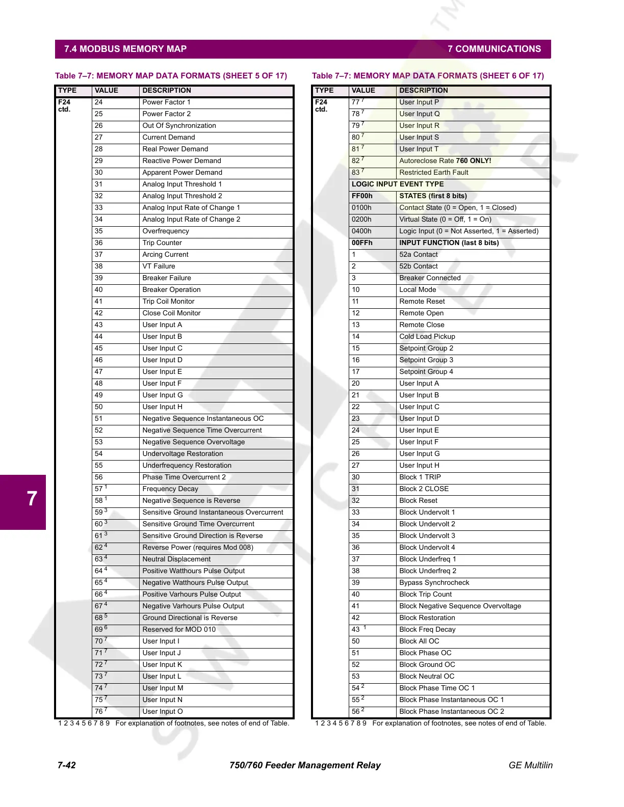
24 Power Factor 1
25 Power Factor 2
26 Out Of Synchronization
27 Current Demand
28 Real Power Demand
29 Reactive Power Demand
30 Apparent Power Demand
31 Analog Input Threshold 1
32 Analog Input Threshold 2
33 Analog Input Rate of Change 1
34 Analog Input Rate of Change 2
35 Overfrequency
36 Trip Counter
37 Arcing Current
38 VT Failure
39 Breaker Failure
40 Breaker Operation
41 Trip Coil Monitor
42 Close Coil Monitor
43 User Input A
44 User Input B
45 User Input C
46 User Input D
47 User Input E
48 User Input F
49 User Input G
50 User Input H
51 Negative Sequence Instantaneous OC
52 Negative Sequence Time Overcurrent
53 Negative Sequence Overvoltage
54 Undervoltage Restoration
55 Underfrequency Restoration
56 Phase Time Overcurrent 2
57
1
Frequency Decay
58
1
Negative Sequence is Reverse
59
3
Sensitive Ground Instantaneous Overcurrent
60
3
Sensitive Ground Time Overcurrent
61
3
Sensitive Ground Direction is Reverse
62
4
Reverse Power (requires Mod 008)
63
4
Neutral Displacement
64
4
Positive Watthours Pulse Output
65
4
Negative Watthours Pulse Output
66
4
Positive Varhours Pulse Output
67
4
Negative Varhours Pulse Output
68
5
Ground Directional is Reverse
69
6
Reserved for MOD 010
70
7
User Input I
71
7
User Input J
72
7
User Input K
73
7
User Input L
74
7
User Input M
75
7
User Input N
76
7
User Input O
Table 7–7: MEMORY MAP DATA FORMATS (SHEET 5 OF 17)
TYPE VALUE DESCRIPTION
1 2 3 4 5 6 7 8 9 For explanation of footnotes, see notes of end of Table.
F24
ctd.
77
7
User Input P
78
7
User Input Q
79
7
User Input R
80
7
User Input S
81
7
User Input T
82
7
Autoreclose Rate 760 ONLY!
83
7
Restricted Earth Fault
LOGIC INPUT EVENT TYPE
FF00h STATES (first 8 bits)
0100h Contact State (0 = Open, 1 = Closed)
0200h Virtual State (0 = Off, 1 = On)
0400h Logic Input (0 = Not Asserted, 1 = Asserted)
00FFh INPUT FUNCTION (last 8 bits)
1 52a Contact
2 52b Contact
3 Breaker Connected
10 Local Mode
11 Remote Reset
12 Remote Open
13 Remote Close
14 Cold Load Pickup
15 Setpoint Group 2
16 Setpoint Group 3
17 Setpoint Group 4
20 User Input A
21 User Input B
22 User Input C
23 User Input D
24 User Input E
25 User Input F
26 User Input G
27 User Input H
30 Block 1 TRIP
31 Block 2 CLOSE
32 Block Reset
33 Block Undervolt 1
34 Block Undervolt 2
35 Block Undervolt 3
36 Block Undervolt 4
37 Block Underfreq 1
38 Block Underfreq 2
39 Bypass Synchrocheck
40 Block Trip Count
41 Block Negative Sequence Overvoltage
42 Block Restoration
43
1
Block Freq Decay
50 Block All OC
51 Block Phase OC
52 Block Ground OC
53 Block Neutral OC
54
2
Block Phase Time OC 1
55
2
Block Phase Instantaneous OC 1
56
2
Block Phase Instantaneous OC 2
Table 7–7: MEMORY MAP DATA FORMATS (SHEET 6 OF 17)
TYPE VALUE DESCRIPTION
1 2 3 4 5 6 7 8 9 For explanation of footnotes, see notes of end of Table.
Courtesy of NationalSwitchgear.com
 Loading...


