GE Multilin 750/760 Feeder Management Relay 7-43
7 COMMUNICATIONS 7.4 MODBUS MEMORY MAP
7
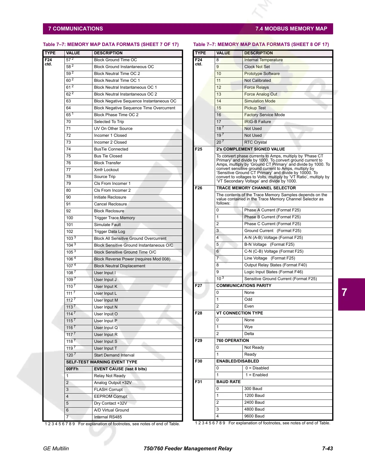
F24
ctd.
57
2
Block Ground Time OC
58
2
Block Ground Instantaneous OC
59
2
Block Neutral Time OC 2
60
2
Block Neutral Time OC 1
61
2
Block Neutral Instantaneous OC 1
62
2
Block Neutral Instantaneous OC 2
63 Block Negative Sequence Instantaneous OC
64 Block Negative Sequence Time Overcurrent
65
1
Block Phase Time OC 2
70 Selected To Trip
71 UV On Other Source
72 Incomer 1 Closed
73 Incomer 2 Closed
74 BusTie Connected
75 Bus Tie Closed
76 Block Transfer
77 Xmfr Lockout
78 Source Trip
79 Cls From Incomer 1
80 Cls From Incomer 2
90 Initiate Reclosure
91 Cancel Reclosure
92 Block Reclosure
100 Trigger Trace Memory
101 Simulate Fault
102 Trigger Data Log
103
3
Block All Sensitive Ground Overcurrent
104
3
Block Sensitive Ground Instantaneous O/C
105
3
Block Sensitive Ground Time O/C
106
4
Block Reverse Power (requires Mod 008)
107
4
Block Neutral Displacement
108
7
User Input I
109
7
User Input J
110
7
User Input K
111
7
User Input L
112
7
User Input M
113
7
User Input N
114
7
User Input O
115
7
User Input P
116
7
User Input Q
117
7
User Input R
118
7
User Input S
119
7
User Input T
120
7
Start Demand Interval
SELF-TEST WARNING EVENT TYPE
00FFh EVENT CAUSE (last 8 bits)
1 Relay Not Ready
2 Analog Output +32V
3 FLASH Corrupt
4 EEPROM Corrupt
5 Dry Contact +32V
6 A/D Virtual Ground
7 Internal RS485
Table 7–7: MEMORY MAP DATA FORMATS (SHEET 7 OF 17)
TYPE VALUE DESCRIPTION
1 2 3 4 5 6 7 8 9 For explanation of footnotes, see notes of end of Table.
F24
ctd.
8 Internal Temperature
9 Clock Not Set
10 Prototype Software
11 Not Calibrated
12 Force Relays
13 Force Analog Out
14 Simulation Mode
15 Pickup Test
16 Factory Service Mode
17 IRIG-B Failure
18
7
Not Used
19
7
Not Used
20
7
RTC Crystal
F25 2's COMPLEMENT SIGNED VALUE
To convert phase currents to Amps, multiply by ‘Phase CT
Primary’ and divide by 1000. To convert ground current to
Amps, multiply by ‘Ground CT Primary’ and divide by 1000. To
convert sensitive ground current to Amps, multiply by
‘Sensitive Ground CT Primary’ and divide by 10000. To
convert to voltages to Volts, multiply by ‘VT Ratio’, multiply by
‘VT Secondary Voltage’ and divide by 1000.
F26 TRACE MEMORY CHANNEL SELECTOR
The contents of the Trace Memory Samples depends on the
value contained in the Trace Memory Channel Selector as
follows:
0 Phase A Current (Format F25)
1 Phase B Current (Format F25)
2 Phase C Current (Format F25)
3 Ground Current (Format F25)
4 A-N (A-B) Voltage (Format F25)
5 B-N Voltage (Format F25)
6 C-N (C-B) Voltage (Format F25)
7 Line Voltage (Format F25)
8 Output Relay States (Format F40)
9 Logic Input States (Format F46)
10
3
Sensitive Ground Current (Format F25)
F27 COMMUNICATIONS PARITY
0 None
1Odd
2 Even
F28 VT CONNECTION TYPE
0 None
1Wye
2Delta
F29 760 OPERATION
0Not Ready
1 Ready
F30 ENABLED/DISABLED
0 0 = Disabled
1 1 = Enabled
F31 BAUD RATE
0 300 Baud
1 1200 Baud
2 2400 Baud
3 4800 Baud
4 9600 Baud
Table 7–7: MEMORY MAP DATA FORMATS (SHEET 8 OF 17)
TYPE VALUE DESCRIPTION
1 2 3 4 5 6 7 8 9 For explanation of footnotes, see notes of end of Table.
Courtesy of NationalSwitchgear.com
 Loading...


