7-44 750/760 Feeder Management Relay GE Multilin
7.4 MODBUS MEMORY MAP 7 COMMUNICATIONS
7
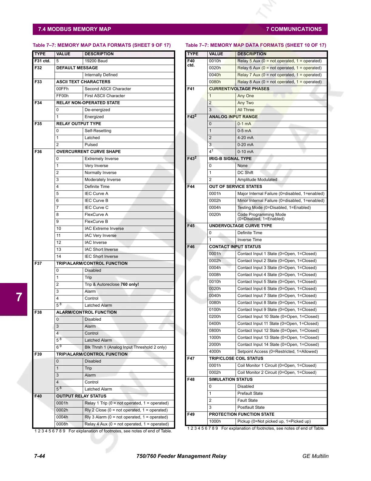
F31 ctd. 5 19200 Baud
F32 DEFAULT MESSAGE
Internally Defined
F33 ASCII TEXT CHARACTERS
00FFh Second ASCII Character
FF00h First ASCII Character
F34 RELAY NON-OPERATED STATE
0 De-energized
1 Energized
F35 RELAY OUTPUT TYPE
0 Self-Resetting
1 Latched
2 Pulsed
F36 OVERCURRENT CURVE SHAPE
0 Extremely Inverse
1 Very Inverse
2 Normally Inverse
3 Moderately Inverse
4 Definite Time
5IEC Curve A
6IEC Curve B
7IEC Curve C
8 FlexCurve A
9 FlexCurve B
10 IAC Extreme Inverse
11 IAC Very Inverse
12 IAC Inverse
13 IAC Short Inverse
14 IEC Short Inverse
F37 TRIP/ALARM/CONTROL FUNCTION
0 Disabled
1Trip
2 Trip & Autoreclose 760 only!
3Alarm
4Control
5
8
Latched Alarm
F38 ALARM/CONTROL FUNCTION
0 Disabled
3Alarm
4Control
5
8
Latched Alarm
6
9
Blk Thrsh 1 (Analog Input Threshold 2 only)
F39 TRIP/ALARM/CONTROL FUNCTION
0 Disabled
1Trip
3Alarm
4Control
5
8
Latched Alarm
F40 OUTPUT RELAY STATUS
0001h Relay 1 Trip (0 = not operated, 1 = operated)
0002h Rly 2 Close (0 = not operated, 1 = operated)
0004h Rly 3 Alarm (0 = not operated, 1 = operated)
0008h Relay 4 Aux (0 = not operated, 1 = operated)
Table 7–7: MEMORY MAP DATA FORMATS (SHEET 9 OF 17)
TYPE VALUE DESCRIPTION
1 2 3 4 5 6 7 8 9 For explanation of footnotes, see notes of end of Table.
F40
ctd.
0010h Relay 5 Aux (0 = not operated, 1 = operated)
0020h Relay 6 Aux (0 = not operated, 1 = operated)
0040h Relay 7 Aux (0 = not operated, 1 = operated)
0080h Relay 8 Aux (0 = not operated, 1 = operated)
F41 CURRENT/VOLTAGE PHASES
1 Any One
2Any Two
3All Three
F42
2
ANALOG INPUT RANGE
0 0-1 mA
1 0-5 mA
24-20 mA
30-20 mA
4
1
0-10 mA
F43
2
IRIG-B SIGNAL TYPE
0 None
1 DC Shift
2 Amplitude Modulated
F44 OUT OF SERVICE STATES
0001h Major Internal Failure (0=disabled, 1=enabled)
0002h Minor Internal Failure (0=disabled, 1=enabled)
0004h Testing Mode (0=Disabled, 1=Enabled)
0020h Code Programming Mode
(0=Disabled, 1=Enabled)
F45 UNDERVOLTAGE CURVE TYPE
0 Definite Time
1 Inverse Time
F46 CONTACT INPUT STATUS
0001h Contact Input 1 State (0=Open, 1=Closed)
0002h Contact Input 2 State (0=Open, 1=Closed)
0004h Contact Input 3 State (0=Open, 1=Closed)
0008h Contact Input 4 State (0=Open, 1=Closed)
0010h Contact Input 5 State (0=Open, 1=Closed)
0020h Contact Input 6 State (0=Open, 1=Closed)
0040h Contact Input 7 State (0=Open, 1=Closed)
0080h Contact Input 8 State (0=Open, 1=Closed)
0100h Contact Input 9 State (0=Open, 1=Closed)
0200h Contact Input 10 State (0=Open, 1=Closed)
0400h Contact Input 11 State (0=Open, 1=Closed)
0800h Contact Input 12 State (0=Open, 1=Closed)
1000h Contact Input 13 State (0=Open, 1=Closed)
2000h Contact Input 14 State (0=Open, 1=Closed)
4000h Setpoint Access (0=Restricted, 1=Allowed)
F47 TRIP/CLOSE COIL STATUS
0001h Coil Monitor 1 Circuit (0=Open, 1=Closed)
0002h Coil Monitor 2 Circuit (0=Open, 1=Closed)
F48 SIMULATION STATUS
0 Disabled
1Prefault State
2 Fault State
3 Postfault State
F49 PROTECTION FUNCTION STATE
1000h Pickup (0=Not picked up, 1=Picked up)
Table 7–7: MEMORY MAP DATA FORMATS (SHEET 10 OF 17)
TYPE VALUE DESCRIPTION
1 2 3 4 5 6 7 8 9 For explanation of footnotes, see notes of end of Table.
Courtesy of NationalSwitchgear.com
 Loading...


