GE Multilin 750/760 Feeder Management Relay 7-45
7 COMMUNICATIONS 7.4 MODBUS MEMORY MAP
7
F49
ctd.
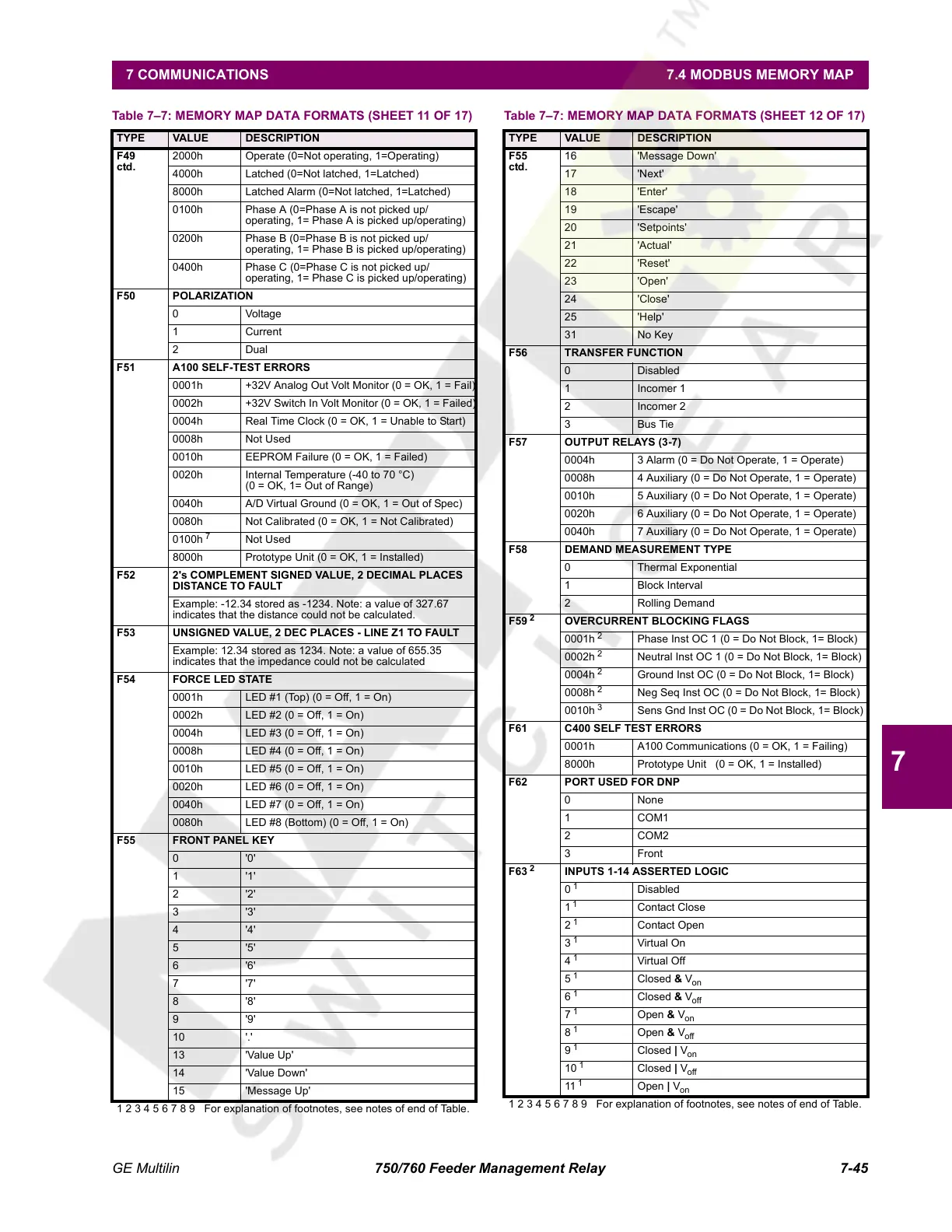
2000h Operate (0=Not operating, 1=Operating)
4000h Latched (0=Not latched, 1=Latched)
8000h Latched Alarm (0=Not latched, 1=Latched)
0100h Phase A (0=Phase A is not picked up/
operating, 1= Phase A is picked up/operating)
0200h Phase B (0=Phase B is not picked up/
operating, 1= Phase B is picked up/operating)
0400h Phase C (0=Phase C is not picked up/
operating, 1= Phase C is picked up/operating)
F50 POLARIZATION
0 Voltage
1 Current
2Dual
F51 A100 SELF-TEST ERRORS
0001h +32V Analog Out Volt Monitor (0 = OK, 1 = Fail)
0002h +32V Switch In Volt Monitor (0 = OK, 1 = Failed)
0004h Real Time Clock (0 = OK, 1 = Unable to Start)
0008h Not Used
0010h EEPROM Failure (0 = OK, 1 = Failed)
0020h Internal Temperature (-40 to 70 °C)
(0 = OK, 1= Out of Range)
0040h A/D Virtual Ground (0 = OK, 1 = Out of Spec)
0080h Not Calibrated (0 = OK, 1 = Not Calibrated)
0100h
7
Not Used
8000h Prototype Unit (0 = OK, 1 = Installed)
F52 2's COMPLEMENT SIGNED VALUE, 2 DECIMAL PLACES
DISTANCE TO FAULT
Example: -12.34 stored as -1234. Note: a value of 327.67
indicates that the distance could not be calculated.
F53 UNSIGNED VALUE, 2 DEC PLACES - LINE Z1 TO FAULT
Example: 12.34 stored as 1234. Note: a value of 655.35
indicates that the impedance could not be calculated
F54 FORCE LED STATE
0001h LED #1 (Top) (0 = Off, 1 = On)
0002h LED #2 (0 = Off, 1 = On)
0004h LED #3 (0 = Off, 1 = On)
0008h LED #4 (0 = Off, 1 = On)
0010h LED #5 (0 = Off, 1 = On)
0020h LED #6 (0 = Off, 1 = On)
0040h LED #7 (0 = Off, 1 = On)
0080h LED #8 (Bottom) (0 = Off, 1 = On)
F55 FRONT PANEL KEY
0'0'
1'1'
2'2'
3'3'
4'4'
5'5'
6'6'
7'7'
8'8'
9'9'
10 '.'
13 'Value Up'
14 'Value Down'
15 'Message Up'
Table 7–7: MEMORY MAP DATA FORMATS (SHEET 11 OF 17)
TYPE VALUE DESCRIPTION
1 2 3 4 5 6 7 8 9 For explanation of footnotes, see notes of end of Table.
F55
ctd.
16 'Message Down'
17 'Next'
18 'Enter'
19 'Escape'
20 'Setpoints'
21 'Actual'
22 'Reset'
23 'Open'
24 'Close'
25 'Help'
31 No Key
F56 TRANSFER FUNCTION
0 Disabled
1 Incomer 1
2 Incomer 2
3Bus Tie
F57 OUTPUT RELAYS (3-7)
0004h 3 Alarm (0 = Do Not Operate, 1 = Operate)
0008h 4 Auxiliary (0 = Do Not Operate, 1 = Operate)
0010h 5 Auxiliary (0 = Do Not Operate, 1 = Operate)
0020h 6 Auxiliary (0 = Do Not Operate, 1 = Operate)
0040h 7 Auxiliary (0 = Do Not Operate, 1 = Operate)
F58 DEMAND MEASUREMENT TYPE
0 Thermal Exponential
1 Block Interval
2 Rolling Demand
F59
2
OVERCURRENT BLOCKING FLAGS
0001h
2
Phase Inst OC 1 (0 = Do Not Block, 1= Block)
0002h
2
Neutral Inst OC 1 (0 = Do Not Block, 1= Block)
0004h
2
Ground Inst OC (0 = Do Not Block, 1= Block)
0008h
2
Neg Seq Inst OC (0 = Do Not Block, 1= Block)
0010h
3
Sens Gnd Inst OC (0 = Do Not Block, 1= Block)
F61 C400 SELF TEST ERRORS
0001h A100 Communications (0 = OK, 1 = Failing)
8000h Prototype Unit (0 = OK, 1 = Installed)
F62 PORT USED FOR DNP
0 None
1COM1
2COM2
3 Front
F63
2
INPUTS 1-14 ASSERTED LOGIC
0
1
Disabled
1
1
Contact Close
2
1
Contact Open
3
1
Virtual On
4
1
Virtual Off
5
1
Closed & V
on
6
1
Closed & V
off
7
1
Open & V
on
8
1
Open & V
off
9
1
Closed | V
on
10
1
Closed | V
off
11
1
Open | V
on
Table 7–7: MEMORY MAP DATA FORMATS (SHEET 12 OF 17)
TYPE VALUE DESCRIPTION
1 2 3 4 5 6 7 8 9 For explanation of footnotes, see notes of end of Table.
Courtesy of NationalSwitchgear.com
 Loading...


