7-46 750/760 Feeder Management Relay GE Multilin
7.4 MODBUS MEMORY MAP 7 COMMUNICATIONS
7
F63
2
ctd.
12
1
Open | V
off
13
1
Closed X V
on
14
1
Closed X V
off
15
1
Open X V
on
16
1
Open X V
off
F64
2
INPUTS 15-20 ASSERTED LOGIC
0
1
Disabled
1
1
Virtual On
2
1
Virtual Off
F65 LOGIC INPUT FUNCTION
0 Disabled
1 Input 1
2 Input 2
3 Input 3
↓↓
20 Input 20
F66 LOGIC INPUT STATE
0Off
1On
F68 RESET TIME MODEL
0 Instantaneous
1 Linear
F69 LOGIC INPUT STATE
0100h Contact State (0 = Open, 1 = Closed)
0200h Virtual State (0 = Off, 1 = On)
0400h Logic Input (0 = Not Asserted, 1 = Asserted)
F70 UNSIGNED VALUE, 3 DECIMAL PLACES
Example: 1.234 stored as 1234
F71 FACTORY SERVICE COMMANDS
0 Clear Any Pending Commands
1 Load Factory Default Setpoints
2 Load Factory Default Calibration Data
3 Clear Diagnostic Data
F72 FORCE HARDWARE
0001h LED's (0=Normal, 1=Use LED force codes)
0002h
8
Reserved
0004h A100 Output Relay Watchdog
(0=Normal, 1=Stop Updating)
0008h C400 Watchdog (0=Normal, 1=Stop Updating)
0010h 485 Communication Port (0=Normal, 1=Echo)
0020h E485 Comm Port (0=Normal, 1=Echo)
0040h A100 Watchdog (0=Normal, 1=Stop Updating)
F73 DYNAMIC OVERCURRENT PRIORITY
0 No Priority Adjustment
1 Voltage Restraint
2 Manual Close
3 Cold Load
4 Autoreclose
F74 DATA LOGGER SAMPLE RATE
0 1 cycle
1 1 second
21 minute
35 minutes
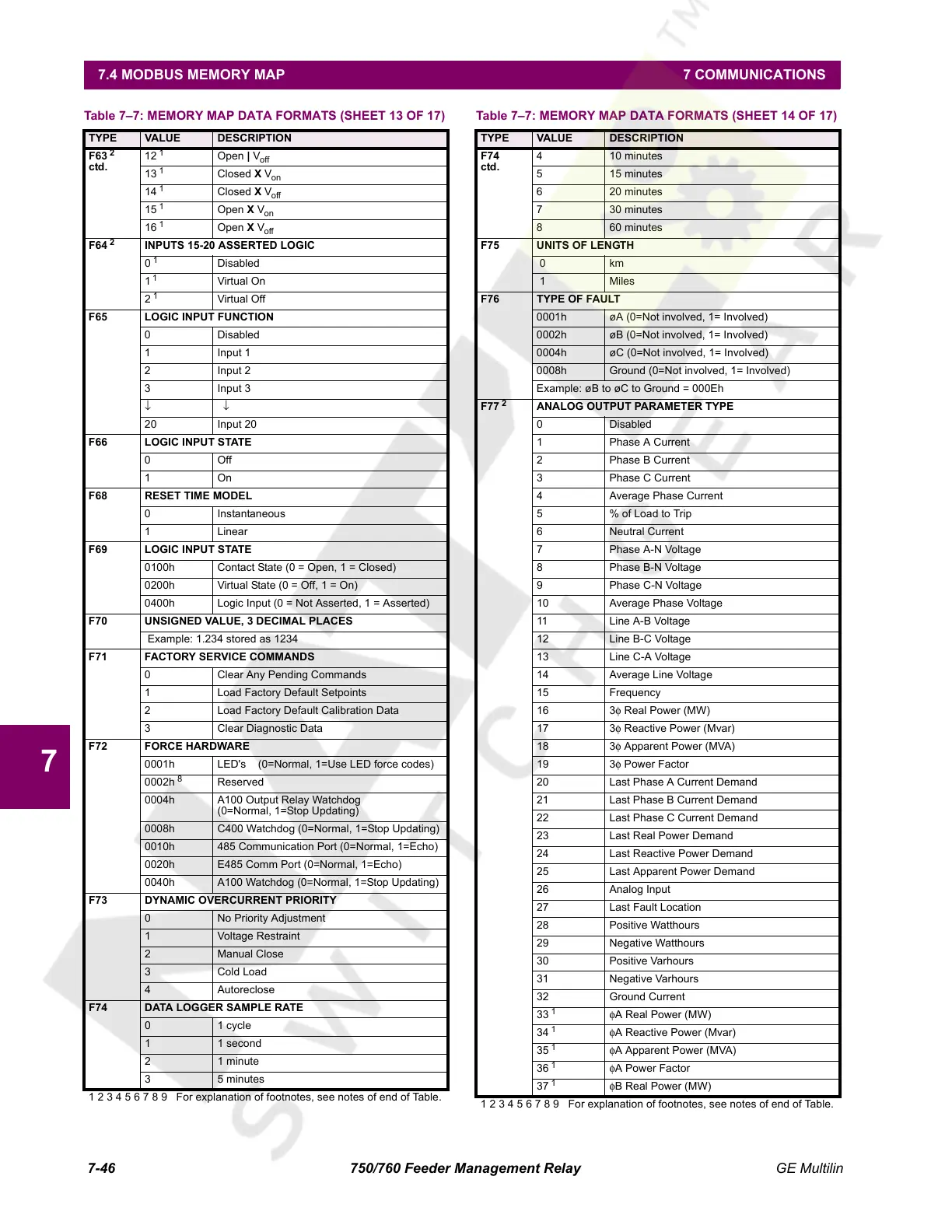
Table 7–7: MEMORY MAP DATA FORMATS (SHEET 13 OF 17)
TYPE VALUE DESCRIPTION
1 2 3 4 5 6 7 8 9 For explanation of footnotes, see notes of end of Table.
F74
ctd.
4 10 minutes
5 15 minutes
6 20 minutes
7 30 minutes
8 60 minutes
F75 UNITS OF LENGTH
0 km
1 Miles
F76 TYPE OF FAULT
0001h øA (0=Not involved, 1= Involved)
0002h øB (0=Not involved, 1= Involved)
0004h øC (0=Not involved, 1= Involved)
0008h Ground (0=Not involved, 1= Involved)
Example: øB to øC to Ground = 000Eh
F77
2
ANALOG OUTPUT PARAMETER TYPE
0 Disabled
1 Phase A Current
2 Phase B Current
3 Phase C Current
4 Average Phase Current
5 % of Load to Trip
6 Neutral Current
7 Phase A-N Voltage
8 Phase B-N Voltage
9 Phase C-N Voltage
10 Average Phase Voltage
11 Line A-B Voltage
12 Line B-C Voltage
13 Line C-A Voltage
14 Average Line Voltage
15 Frequency
16 3φ Real Power (MW)
17 3φ Reactive Power (Mvar)
18 3φ Apparent Power (MVA)
19 3φ Power Factor
20 Last Phase A Current Demand
21 Last Phase B Current Demand
22 Last Phase C Current Demand
23 Last Real Power Demand
24 Last Reactive Power Demand
25 Last Apparent Power Demand
26 Analog Input
27 Last Fault Location
28 Positive Watthours
29 Negative Watthours
30 Positive Varhours
31 Negative Varhours
32 Ground Current
33
1
φA Real Power (MW)
34
1
φA Reactive Power (Mvar)
35
1
φA Apparent Power (MVA)
36
1
φA Power Factor
37
1
φB Real Power (MW)
Table 7–7: MEMORY MAP DATA FORMATS (SHEET 14 OF 17)
TYPE VALUE DESCRIPTION
1 2 3 4 5 6 7 8 9 For explanation of footnotes, see notes of end of Table.
Courtesy of NationalSwitchgear.com
 Loading...


