GE Multilin 750/760 Feeder Management Relay 7-53
7 COMMUNICATIONS 7.5 DNP COMMUNICATIONS
7
b) BINARY OUTPUT / CONTROL RELAY OUTPUT
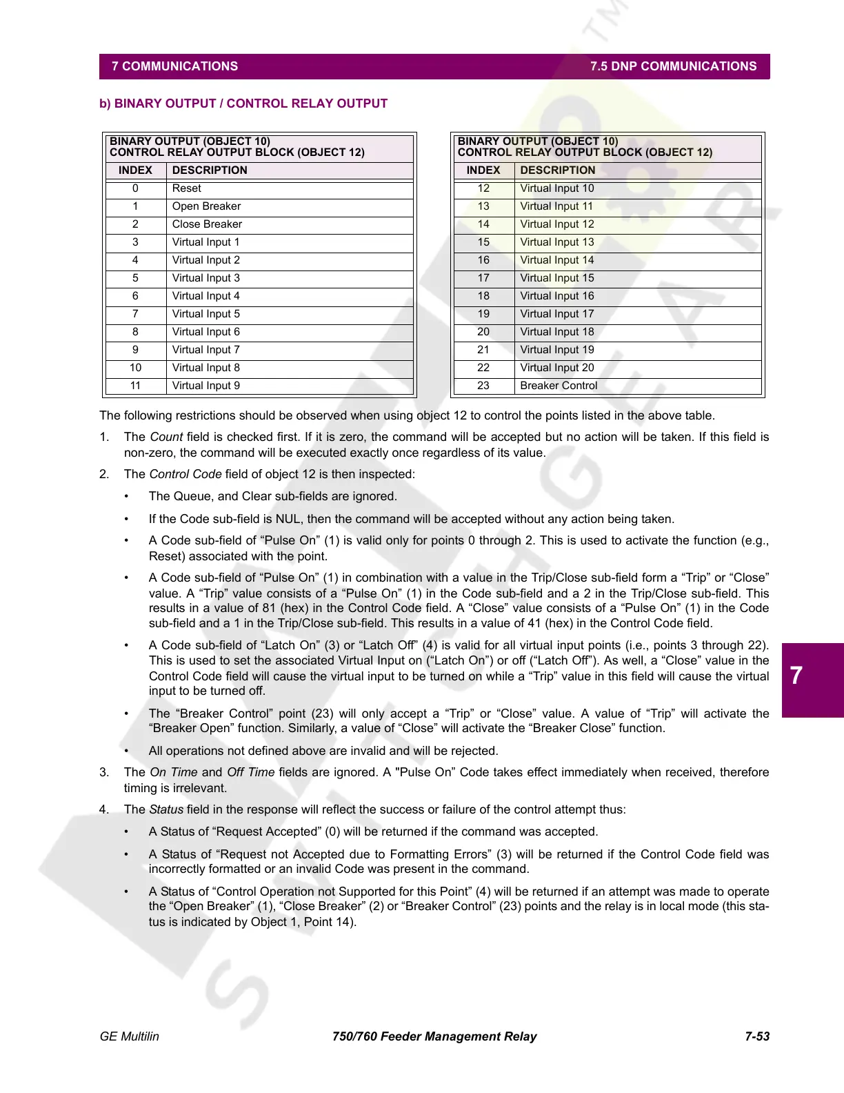
The following restrictions should be observed when using object 12 to control the points listed in the above table.
1. The Count field is checked first. If it is zero, the command will be accepted but no action will be taken. If this field is
non-zero, the command will be executed exactly once regardless of its value.
2. The Control Code field of object 12 is then inspected:
• The Queue, and Clear sub-fields are ignored.
• If the Code sub-field is NUL, then the command will be accepted without any action being taken.
• A Code sub-field of “Pulse On” (1) is valid only for points 0 through 2. This is used to activate the function (e.g.,
Reset) associated with the point.
• A Code sub-field of “Pulse On” (1) in combination with a value in the Trip/Close sub-field form a “Trip” or “Close”
value. A “Trip” value consists of a “Pulse On” (1) in the Code sub-field and a 2 in the Trip/Close sub-field. This
results in a value of 81 (hex) in the Control Code field. A “Close” value consists of a “Pulse On” (1) in the Code
sub-field and a 1 in the Trip/Close sub-field. This results in a value of 41 (hex) in the Control Code field.
• A Code sub-field of “Latch On” (3) or “Latch Off” (4) is valid for all virtual input points (i.e., points 3 through 22).
This is used to set the associated Virtual Input on (“Latch On”) or off (“Latch Off”). As well, a “Close” value in the
Control Code field will cause the virtual input to be turned on while a “Trip” value in this field will cause the virtual
input to be turned off.
• The “Breaker Control” point (23) will only accept a “Trip” or “Close” value. A value of “Trip” will activate the
“Breaker Open” function. Similarly, a value of “Close” will activate the “Breaker Close” function.
• All operations not defined above are invalid and will be rejected.
3. The On Time and Off Time fields are ignored. A "Pulse On” Code takes effect immediately when received, therefore
timing is irrelevant.
4. The Status field in the response will reflect the success or failure of the control attempt thus:
• A Status of “Request Accepted” (0) will be returned if the command was accepted.
• A Status of “Request not Accepted due to Formatting Errors” (3) will be returned if the Control Code field was
incorrectly formatted or an invalid Code was present in the command.
• A Status of “Control Operation not Supported for this Point” (4) will be returned if an attempt was made to operate
the “Open Breaker” (1), “Close Breaker” (2) or “Breaker Control” (23) points and the relay is in local mode (this sta-
tus is indicated by Object 1, Point 14).
BINARY OUTPUT (OBJECT 10)
CONTROL RELAY OUTPUT BLOCK (OBJECT 12)
BINARY OUTPUT (OBJECT 10)
CONTROL RELAY OUTPUT BLOCK (OBJECT 12)
INDEX DESCRIPTION INDEX DESCRIPTION
0 Reset 12 Virtual Input 10
1 Open Breaker 13 Virtual Input 11
2 Close Breaker 14 Virtual Input 12
3 Virtual Input 1 15 Virtual Input 13
4 Virtual Input 2 16 Virtual Input 14
5 Virtual Input 3 17 Virtual Input 15
6 Virtual Input 4 18 Virtual Input 16
7 Virtual Input 5 19 Virtual Input 17
8 Virtual Input 6 20 Virtual Input 18
9 Virtual Input 7 21 Virtual Input 19
10 Virtual Input 8 22 Virtual Input 20
11 Virtual Input 9 23 Breaker Control
Courtesy of NationalSwitchgear.com
 Loading...


