7-58 750/760 Feeder Management Relay GE Multilin
7.5 DNP COMMUNICATIONS 7 COMMUNICATIONS
7
Notes:
1. To support existing SCADA hardware that is not capable of 32-bit data reads, the upper and lower 16-bit portions of all
time and date values have been assigned to separate points. To read a date or time, it is necessary to read both the
upper and lower 16-bit portions, concatenate these two values to form a 32-bit value and interpret the result in the for-
mat associated with the point (i.e., F22 for time, F23 for date).
2. Points which have an assigned event class will generate an event object as a result of any change in the point’s value
unless otherwise noted.
3. An event object will be generated if the point’s value changes by a minimum of 2% of its previous value.
4. An event object will be generated if the system frequency changes by 0.04 Hz or more.
5. There are two defined maps for Analog Output points. The map that is used is specified by the setting of the “DNP
Point Mapping” setpoint at Modbus address 10DBh. This setpoint may be set to a value of “Disabled” or “Enabled”.
When “Disabled”, only the preassigned Analog Output points are available beginning at point index 0.
When “Enabled”, the User Map Values are assigned to points 0 through 119 with the preassigned Analog Outputs fol-
lowing beginning with Point Index 120. The value read from points 0 through 119 will depend upon the value pro-
grammed into the corresponding User Map Address setpoint (note that programming of these setpoints can only be
accomplished via Modbus). Refer to Section 7.3.7: Accessing Data via the User Map on page 7–11 for more informa-
tion.
Please note that changes in User Map Values never generate event objects.
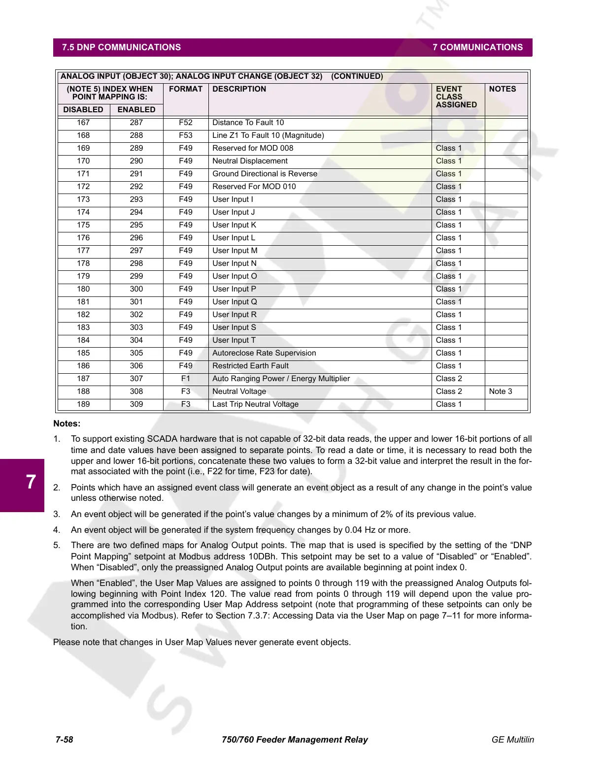
167 287 F52 Distance To Fault 10
168 288 F53 Line Z1 To Fault 10 (Magnitude)
169 289 F49 Reserved for MOD 008 Class 1
170 290 F49 Neutral Displacement Class 1
171 291 F49 Ground Directional is Reverse Class 1
172 292 F49 Reserved For MOD 010 Class 1
173 293 F49 User Input I Class 1
174 294 F49 User Input J Class 1
175 295 F49 User Input K Class 1
176 296 F49 User Input L Class 1
177 297 F49 User Input M Class 1
178 298 F49 User Input N Class 1
179 299 F49 User Input O Class 1
180 300 F49 User Input P Class 1
181 301 F49 User Input Q Class 1
182 302 F49 User Input R Class 1
183 303 F49 User Input S Class 1
184 304 F49 User Input T Class 1
185 305 F49 Autoreclose Rate Supervision Class 1
186 306 F49 Restricted Earth Fault Class 1
187 307 F1 Auto Ranging Power / Energy Multiplier Class 2
188 308 F3 Neutral Voltage Class 2 Note 3
189 309 F3 Last Trip Neutral Voltage Class 1
ANALOG INPUT (OBJECT 30); ANALOG INPUT CHANGE (OBJECT 32) (CONTINUED)
(NOTE 5) INDEX WHEN
POINT MAPPING IS:
FORMAT DESCRIPTION EVENT
CLASS
ASSIGNED
NOTES
DISABLED ENABLED
Courtesy of NationalSwitchgear.com
 Loading...


