GE Multilin 750/760 Feeder Management Relay 8-21
8 COMMISSIONING TESTS 8.4 PROTECTION SCHEMES
8
3. Repeat Steps 1 and 2 for logic inputs "Block Neutral O/C", "Block All O/C" and “Block 1 Trip Relay” as required.
c) NEUTRAL IOC 1
The procedure to test this element is identical to that outlined in Phase TOC 1 on page 8–16, except that current is injected
into any one phase, and the element is not subject to the “phases required for operation”, “linear reset timing”, and “voltage
restrained time overcurrent” tests.
The blocking from logic inputs check is different from that for Phase TOC 1 and is performed as follows:
1. Inject current to cause a pickup.
2. Assert a logic input to provide a "Block Neutral Inst 1". The Pickup LED should immediately go out.
3. Repeat 1 and 2 for logic inputs "Block Neutral O/C", "Block All O/C" and “Block 1 Trip Relay” as required.
d) NEUTRAL IOC 2
The procedure to test this element is identical to that outlined in Phase TOC 1 on page 8–16, except that current is injected
into any one phase, and the element is not subject to the “phases required for operation”, “linear reset timing”, and “voltage
restrained time overcurrent” checks.
The blocking from logic inputs check is different from that for Phase TOC 1 and is performed as follows:
1. Inject current to cause a pickup.
2. Assert a logic input to provide a "Block Neutral Inst 2". The Pickup LED should immediately go out.
3. Repeat Steps 1 and 2 for logic inputs "Block Neutral O/C", "Block All O/C" and “Block 1 Trip Relay” as required.
e) NEUTRAL DIRECTIONAL OC
If dual polarizing is required, check the operation of the voltage and current polarized elements individually as outlined
below, then check the overall dual polarized response as outlined at the end of this section.
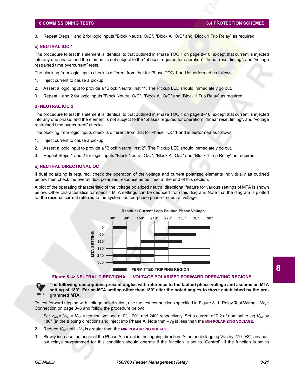
A plot of the operating characteristic of the voltage polarized neutral directional feature for various settings of MTA is shown
below. Other characteristics for specific MTA settings can be deduced from this diagram. Note that the diagram is plotted
for the residual current referred to the system faulted-phase phase-to-neutral voltage.
Figure 8–4: NEUTRAL DIRECTIONAL – VOLTAGE POLARIZED FORWARD OPERATING REGIONS
The following descriptions present angles with reference to the faulted phase voltage and assume an MTA
setting of 180°. For an MTA setting other than 180° alter the noted angles to those established by the pro-
grammed MTA.
To test forward tripping with voltage polarization, use the test connections specified in Figure 8–1: Relay Test Wiring – Wye
Connection on page 8–3 and follow the procedure below:
1. Set V
an
= V
bn
= V
cn
= nominal voltage at 0°, 120°, and 240° respectively. Set a current of 0.2 of nominal to lag V
an
by
180° (in the tripping direction) and inject into Phase A. Note that –V
0
is less than the MIN POLARIZING VOLTAGE.
2. Reduce V
an
until –V
0
is greater than the MIN POLARIZING VOLTAGE.
3. Slowly increase the angle of the Phase A current in the lagging direction. At an angle lagging Van by 270° ±2°, any out-
put relays programmed for this condition should operate if the function is set to “Control”. If the function is set to
Residual Current Lags Faulted Phase Voltage
= PERMITTED TRIPPING REGION
MTA SETTING
0°
60°
120°
180°
240°
300°
30°
90°
150° 210° 270° 330° 30°
90°
NOTE
Courtesy of NationalSwitchgear.com
 Loading...


