8-22 750/760 Feeder Management Relay GE Multilin
8.4 PROTECTION SCHEMES 8 COMMISSIONING TESTS
8
"Alarm", check that the Alarm and Message LEDs are flashing, the Neutral Directional Reverse alarm message is dis-
played, and any output relays programmed for this condition are operated.
4. Continue to increase the lagging angle through 0°, until the block message disappears at an angle lagging V
an
by 90°
±2°. Turn the current off.
5. If desired, repeat the above Steps 1 through 4 for Phases B and C using I
b
with faulted phase voltage V
bn
and I
c
with
faulted phase voltage V
cn
.
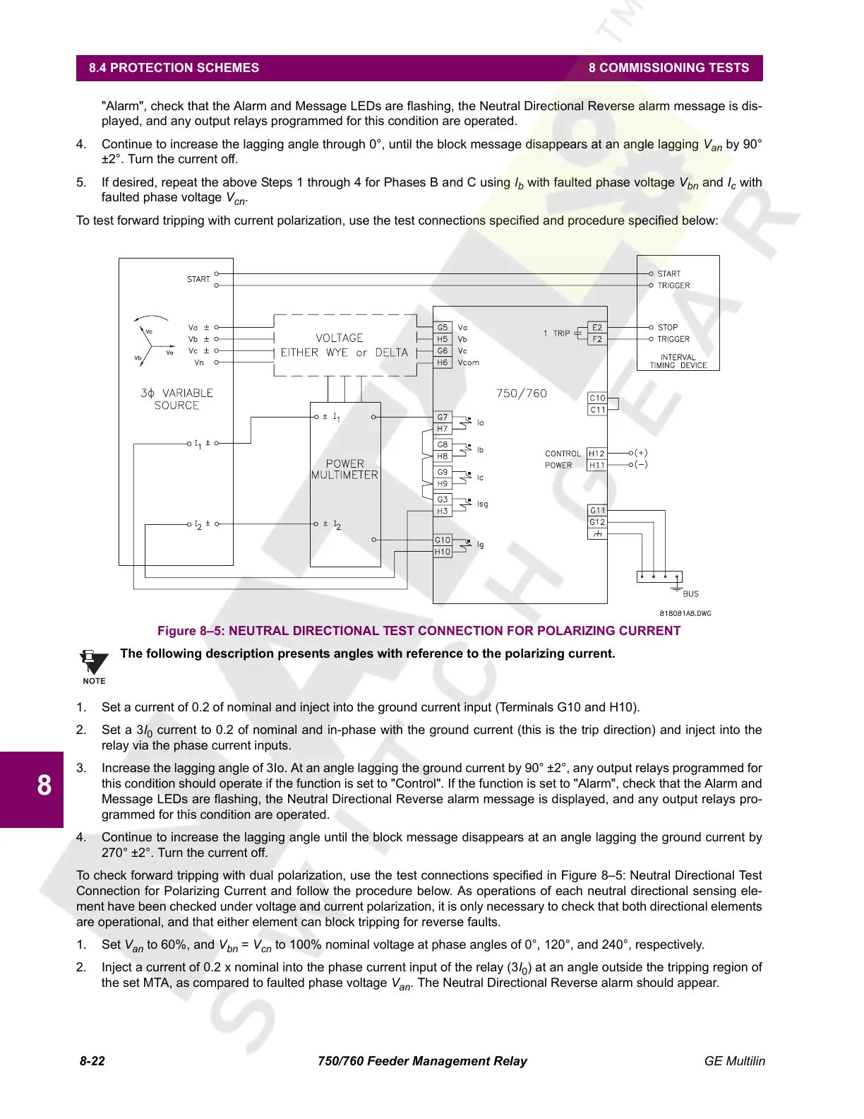
To test forward tripping with current polarization, use the test connections specified and procedure specified below:
Figure 8–5: NEUTRAL DIRECTIONAL TEST CONNECTION FOR POLARIZING CURRENT
The following description presents angles with reference to the polarizing current.
1. Set a current of 0.2 of nominal and inject into the ground current input (Terminals G10 and H10).
2. Set a 3I
0
current to 0.2 of nominal and in-phase with the ground current (this is the trip direction) and inject into the
relay via the phase current inputs.
3. Increase the lagging angle of 3Io. At an angle lagging the ground current by 90° ±2°, any output relays programmed for
this condition should operate if the function is set to "Control". If the function is set to "Alarm", check that the Alarm and
Message LEDs are flashing, the Neutral Directional Reverse alarm message is displayed, and any output relays pro-
grammed for this condition are operated.
4. Continue to increase the lagging angle until the block message disappears at an angle lagging the ground current by
270° ±2°. Turn the current off.
To check forward tripping with dual polarization, use the test connections specified in Figure 8–5: Neutral Directional Test
Connection for Polarizing Current and follow the procedure below. As operations of each neutral directional sensing ele-
ment have been checked under voltage and current polarization, it is only necessary to check that both directional elements
are operational, and that either element can block tripping for reverse faults.
1. Set V
an
to 60%, and V
bn
= V
cn
to 100% nominal voltage at phase angles of 0°, 120°, and 240°, respectively.
2. Inject a current of 0.2 x nominal into the phase current input of the relay (3I
0
) at an angle outside the tripping region of
the set MTA, as compared to faulted phase voltage V
an
. The Neutral Directional Reverse alarm should appear.
NOTE
Courtesy of NationalSwitchgear.com
 Loading...


