GE Multilin 750/760 Feeder Management Relay 8-53
8 COMMISSIONING TESTS 8.6 CONTROL SCHEMES
8
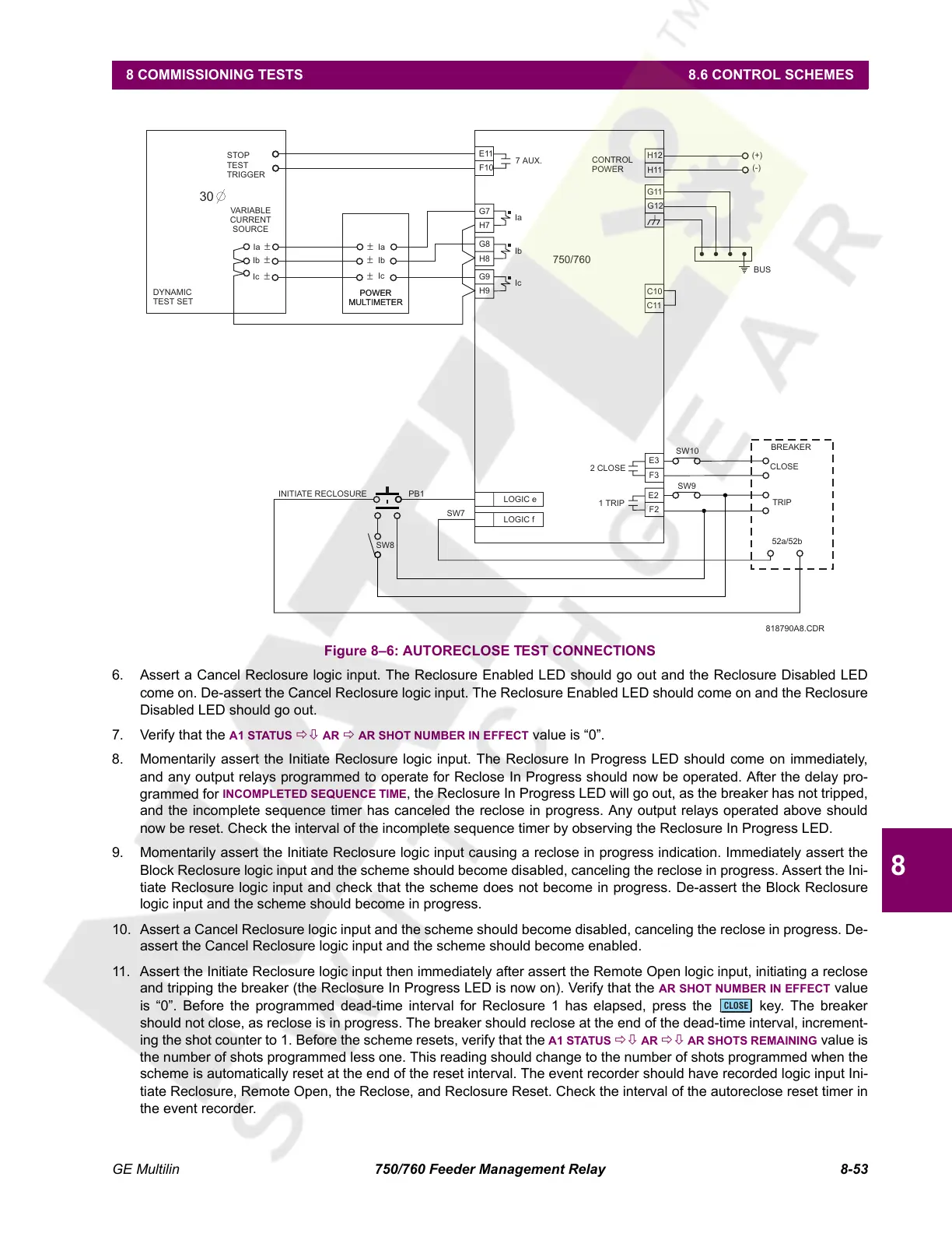
Figure 8–6: AUTORECLOSE TEST CONNECTIONS
6. Assert a Cancel Reclosure logic input. The Reclosure Enabled LED should go out and the Reclosure Disabled LED
come on. De-assert the Cancel Reclosure logic input. The Reclosure Enabled LED should come on and the Reclosure
Disabled LED should go out.
7. Verify that the A1 STATUS ÖØ AR Ö AR SHOT NUMBER IN EFFECT value is “0”.
8. Momentarily assert the Initiate Reclosure logic input. The Reclosure In Progress LED should come on immediately,
and any output relays programmed to operate for Reclose In Progress should now be operated. After the delay pro-
grammed for
INCOMPLETED SEQUENCE TIME, the Reclosure In Progress LED will go out, as the breaker has not tripped,
and the incomplete sequence timer has canceled the reclose in progress. Any output relays operated above should
now be reset. Check the interval of the incomplete sequence timer by observing the Reclosure In Progress LED.
9. Momentarily assert the Initiate Reclosure logic input causing a reclose in progress indication. Immediately assert the
Block Reclosure logic input and the scheme should become disabled, canceling the reclose in progress. Assert the Ini-
tiate Reclosure logic input and check that the scheme does not become in progress. De-assert the Block Reclosure
logic input and the scheme should become in progress.
10. Assert a Cancel Reclosure logic input and the scheme should become disabled, canceling the reclose in progress. De-
assert the Cancel Reclosure logic input and the scheme should become enabled.
11. Assert the Initiate Reclosure logic input then immediately after assert the Remote Open logic input, initiating a reclose
and tripping the breaker (the Reclosure In Progress LED is now on). Verify that the
AR SHOT NUMBER IN EFFECT value
is “0”. Before the programmed dead-time interval for Reclosure 1 has elapsed, press the key. The breaker
should not close, as reclose is in progress. The breaker should reclose at the end of the dead-time interval, increment-
ing the shot counter to 1. Before the scheme resets, verify that the
A1 STATUS ÖØ AR ÖØ AR SHOTS REMAINING value is
the number of shots programmed less one. This reading should change to the number of shots programmed when the
scheme is automatically reset at the end of the reset interval. The event recorder should have recorded logic input Ini-
tiate Reclosure, Remote Open, the Reclose, and Reclosure Reset. Check the interval of the autoreclose reset timer in
the event recorder.
750/760
Ia
Ib
Ia
Ib
POWER
MULTIMETER
VARIABLE
CURRENT
SOURCE
±
±
±
±
Ic
Ic
±
±
BUS
G7
H7
Ia
G8
H8
Ib
G9
H9
Ic
BREAKER
CLOSE
TRIP
1 TRIP
2CLOSE
52a/52b
CONTROL
POWER
(+)
(-)
POWER
MULTIMETER
INITIATE RECLOSURE
LOGIC e
LOGIC f
PB1
SW8
SW7
SW9
SW10
818790A8.CDR
E11
F10
STOP
TEST
TRIGGER
30
DYNAMIC
TEST SET
7 AUX.
H12
H11
G11
G12
E3
F3
E2
F2
C10
C11
CLOSE
Courtesy of NationalSwitchgear.com
 Loading...


