GE VOLUSON
i / VOLUSON
e
D
IRECTION KTI106052, REVISION 10 SERVICE MANUAL
3-36 Section 3-5 - Connection of Auxiliary Devices
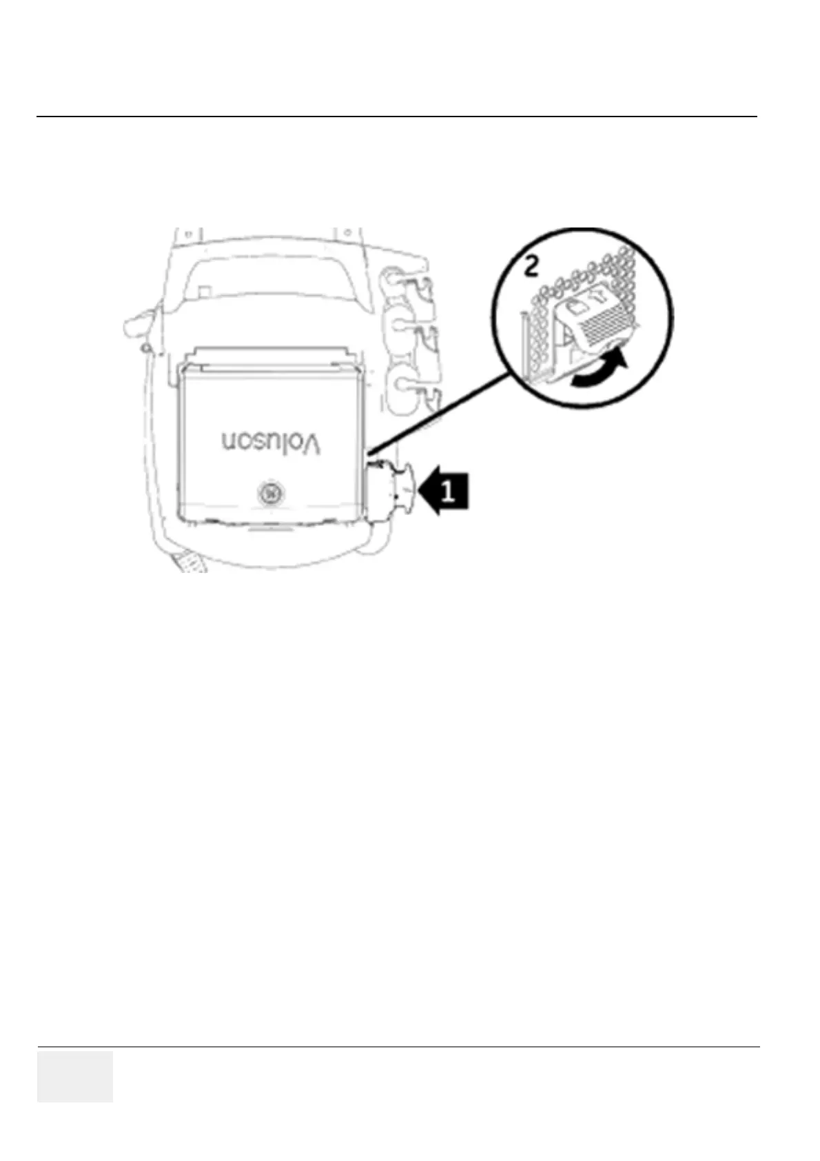
3-5-3-1 Attaching the Voluson i / Voluson e to the Voluson Station (cont’d)
If applicable, connect the Probe Mux Box.
3.) Push the probe connector into the probe socket of the Voluson i / Voluson e.
4.) Lift the system’s locking lever upwards to lock the probe connector.
The Probe Mux Box enables the connection of up to 3 probes to the Voluson i / Voluson e.
5.) Connect the cable to the rear of the Voluson i / Voluson e. The cable is listed below:
• LAN cable - Connect the ethernet cable, routing from the LAN isolation box, into the network port
of the Voluson i / Voluson e.
6.) Mount and connect other peripherals as described in Section 3-5-3-8 and Section 3-5-3-9.
7.) Connect the main power cable to the Power Supply of the Voluson Station; the other end connect
to a hospital-grade main power outlet with the proper rated voltage.
Figure 3-39 Voluson i / Voluson e attached to the Voluson Station
 Loading...


