GE VOLUSON
i / VOLUSON
e
D
IRECTION KTI106052, REVISION 10 SERVICE MANUAL
8-74 Section 8-20 - Replacement of the Voluson Station Components
8-20-14 Replacement of the Top Column Back Cover
8-20-14-1 Manpower
One person, 15 minutes
8-20-14-2 Tools
Phillips screwdriver 1
8-20-14-3 Preparations
1.) Power Off/Shutdown the system as described in Section 3-6-3 on page 3-72.
2.) Remove the Top Shelf Additional Bottom Cover as described in Section 8-20-12 on page 8-72 or
remove the optional Probe Mux Bos as described in Section 8-20-9 on page 8-68.
3.) Remove the Top Shelf Bottom Rear Cover as described in Section 8-20-13 on page 8-73.
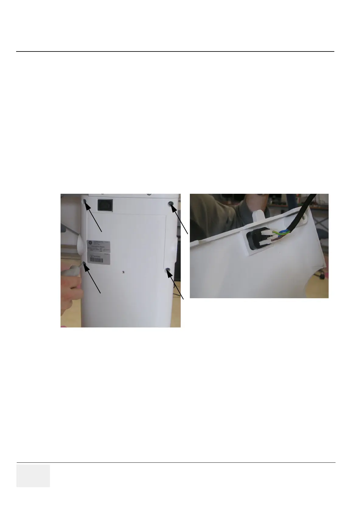
8-20-14-4 Top Column Back Cover - Removal Procedure
1.) Screw off the 4 screws and disconnect the power cable.
2.) Carefully remove the Top Column Back Cover.
8-20-14-5 Top Column Back Cover - Installation Procedure
1.) Place the new Top Column Back Cover, connect the power cable and fasten it with the 4 screws.
2.) Mount the Top Shelf Bottom Rear Cover as described in Section 8-20-13-5 on page 8-73.
3.) Mount the Top Shelf Additional Bottom Cover as described in Section 8-20-12-5 on page 8-72 or
mount the optional Probe Mux Box as described in Section 8-20-9-5 on page 8-69.
Figure 8-97 unscrew the 4 screws / disconnect the power cable
 Loading...


