GE VOLUSON
i / VOLUSON
e
D
IRECTION KTI106052, REVISION 10 SERVICE MANUAL
Chapter 8 - Replacement Procedures 8-69
8-20-9-4 Probe Mux Box - Removal Procedure (cont’d)
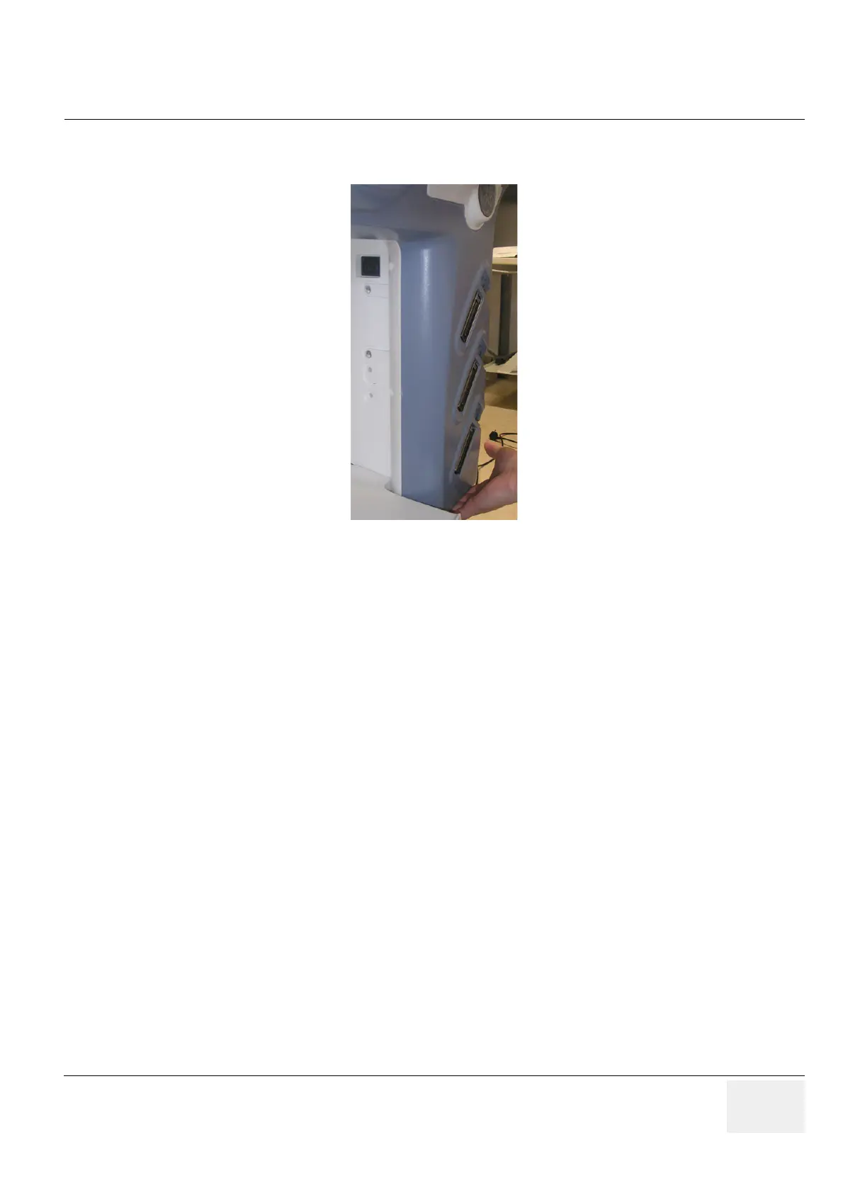
3.) With both hands swing the Probe Box out away from the Voluson Station.
8-20-9-5 Probe Mux Box - Installation Procedure
4.) Fasten the Box on the Voluson Station with the screws as shown in Figure 8-89 on page 8-68.
5.) Reconnect the Probe Box as shown in Figure 8-88 on page 8-68.
Figure 8-90 carefully remove the Probe Box
 Loading...


