4
Applicator description Operating instructions HERMA 400
26/154 3.28 US (130519)
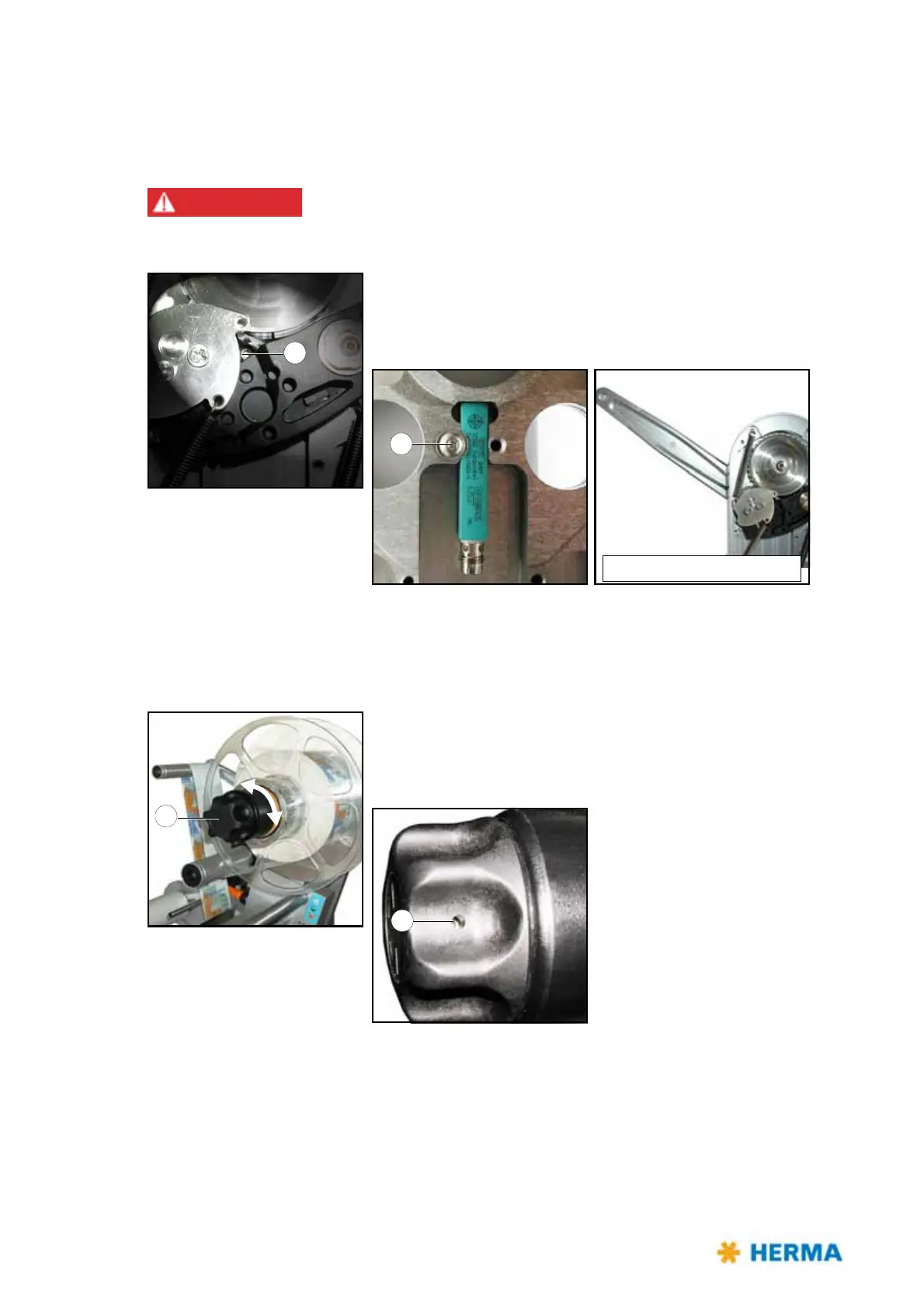
Replacing the proximity switch
If your unwinder is equipped with a proximity switch for detecting end of reel proceed as follows when
replacing a defective switch:
Risk of electric shock! Disconnect all sources of supply and wait for five
minutes before opening the rear cover or touching the connector pins!
Electrocution may occur.
> After opening the cover loosen screw 9
on the back (do not
remove!). Take out the proximity switch and insert a new one.
Fasten screw 9 afterwards.
Screw 9 is accessible if the pendulum lever is in its basic position.
Replacing the handle
If after a very long time of use clamping of the reel with handle 1 does not function properly anymore
proceed as follows when preplacing a worn handle:
> Turn handle 1 completely to the left (maximum of five steps) to
unclamp the unit and make screw 10 accessible.
Loosen screw 10 (do not remove!), retract the handle, insert new
handle and fasten screw 10 afterwards.