4
Applicator description Operating instructions HERMA 400
44/154 3.28 US (130519)
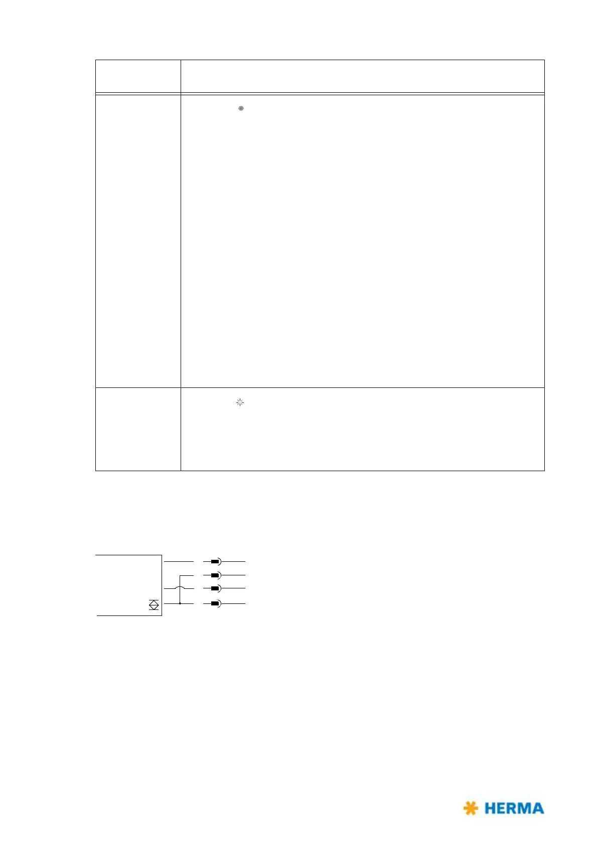
Connection Diagram
>15s, <20s
LED is off
, adjusting the offset.
After releasing the button a blink sequence indicates the offset currently set
(the standard val
ue for paper labels is 6, for metal labels 10).
Press button 1x thereafter for a
short time = offset +1,
keep button pressed 1x for more than 2
seconds = offset –1.
As in the beginning, after every change a
blink sequence will indicate the value
currently set.
The end of function is reached automatically 10 seconds after the last releasing
of the button.
The offset must be changed only in exceptional
cases, as a rule only at speeds
of ~4.700“/min (120 m/min) or more. In such case the gap between the labels
may not be detected reliably and the sensitivity must be adjusted.
Consequently decrease the offset with very thin labels of below 50 μ and
increase
it with very thick labels of more than 150 μ correspondingly.
Offsets can be adjusted from 1 through 20.
>20s
LED is on
, return to factoy setting
The factory setting is: paper label, off
set 6 (offset 10 with metal labels).
After end of function (releasing the button)
a blink code is shown (2x slowly).
Buttonpress
du
ration
Function triggered / activated
15–30V DC +
GND
FS03
1
2
3
4
br/bn
ws/wh
bl/bu
sw/bk