8.4 Using Analog and Waveform D/A Output Options (must be factory installed before
133
8
Chapter 8 Connecting External Devices
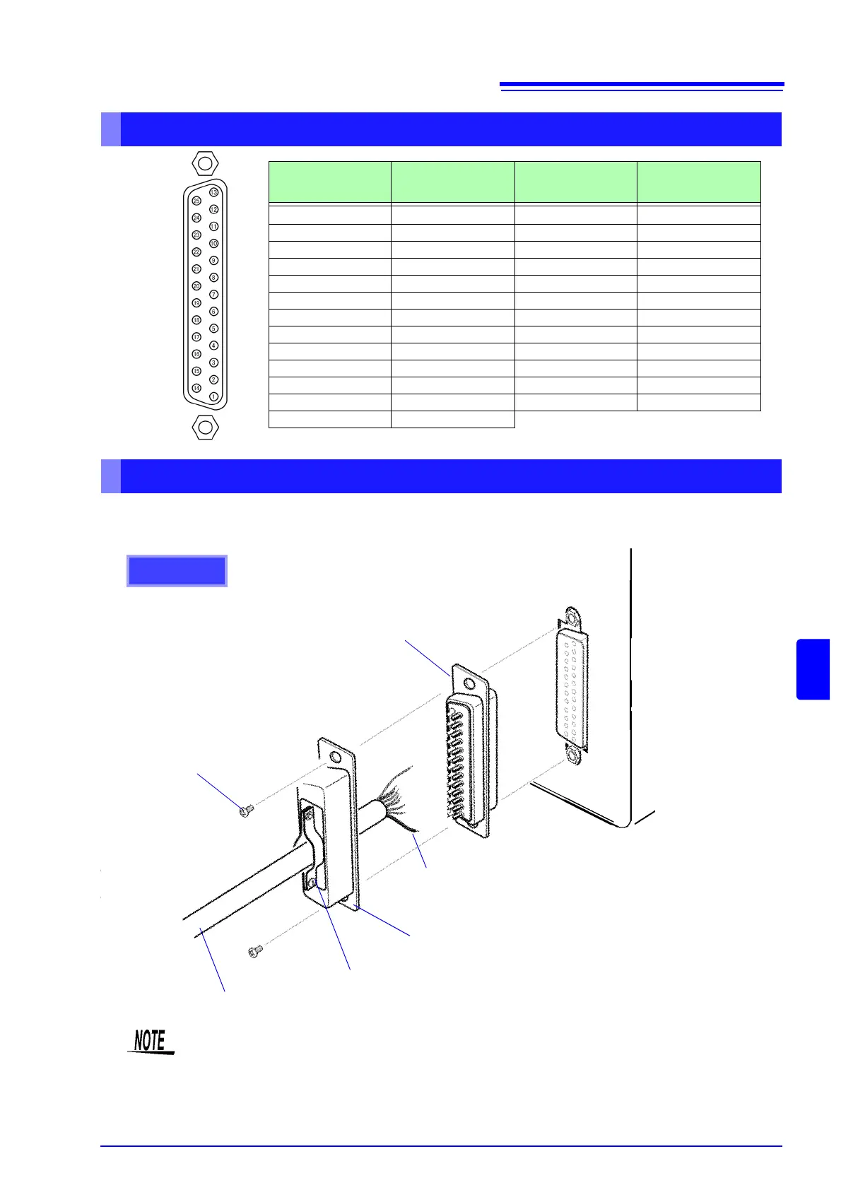
User the supplied connector (DB-25P-NR, D819678-2R Japan Aviation Electronics Industry,Ltd) or
equivalent connector to connect to the external control and output terminals.
D/A Output Connector Pin-Out
Pin No.
Output
( ) waveform output
content
Pin No. Output
1GND14GND
2 D/A1 (U1) 15 D/A9
3 D/A2 (I1) 16 D/A10
4 D/A3 (U2) 17 D/A11
5 D/A4 (I2) 18 D/A12
6 D/A5 (U3) 19 D/A13
7 D/A6 (I3) 20 D/A14
8 D/A7 (U4) 21 D/A15
9 D/A8 (I4) 22 D/A16
10 GND 23 GND
11 GND 24 GND
12 GND 25 GND
13 GND
Instrument
Rear Panel
How to connect D/A output terminals
Soldering
Cord
Connector cover
Cable fixture
Shielded cable
Screw
Rear panel
• Solder the cord securely.
• Fix the connector and connector cover by the supplied screws (M2.6x6).
• Hold the connector cover when connecting or disconnecting the connector.
• Use the shielded cable for output and external control.
• Connect to the connector cover or cable fixture if the cable's shield is not grounded.