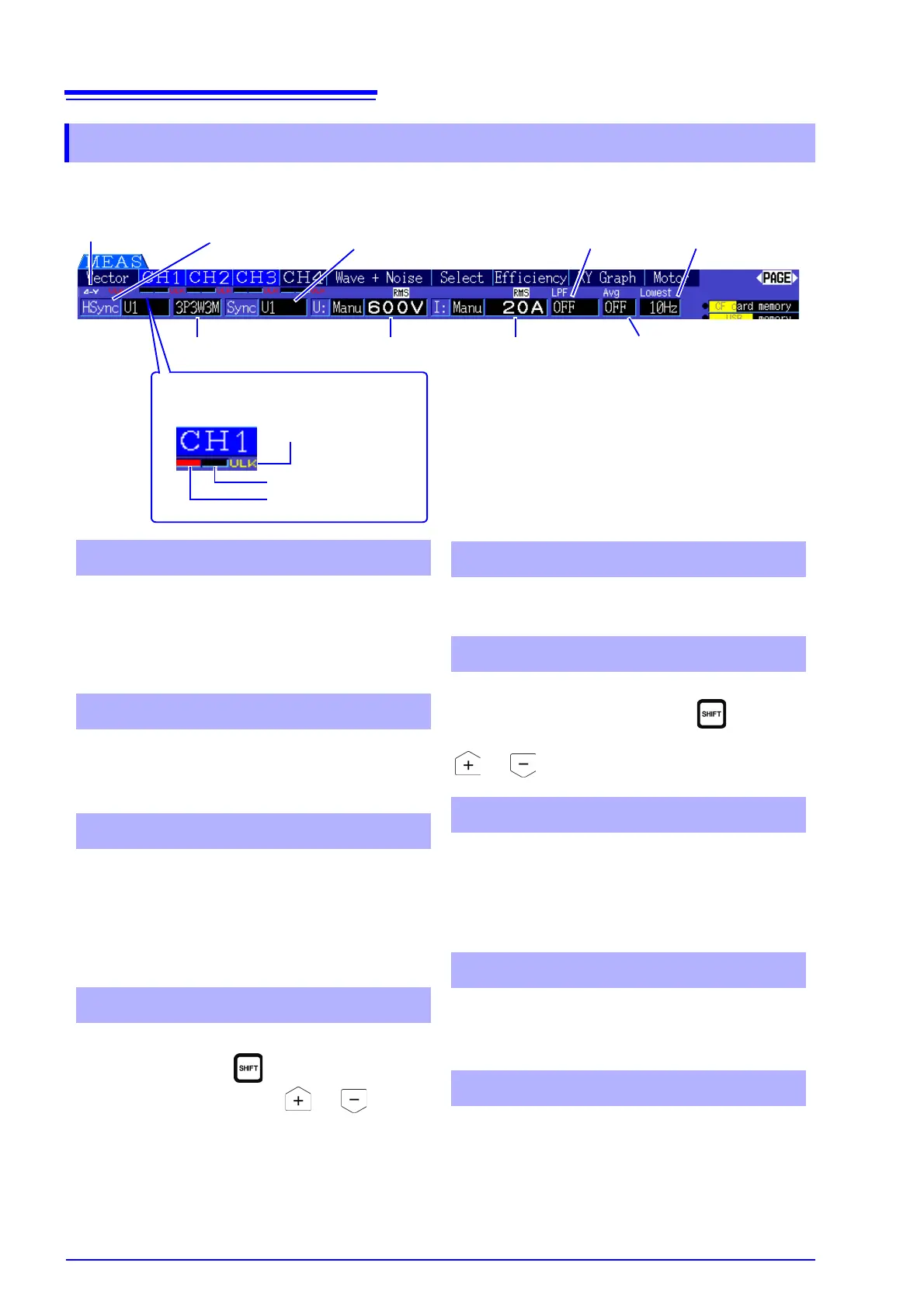
2.3.2 Measurement Screen
Current peak overrange
Voltage peakoverrange
Sync Unlocked
Peak Over display indicators
1
These indicators appear in red at the bottom of
each channel page tab (CH1 to CH4). These indi-
cate (from the left) when voltage and current peaks
ranges are exceeded (p. 40), and when synchroni-
zation is unlocked (p. 48).
Indicates the selected wiring mode (p. 30). The wir-
ing mode (phase system selection) must be set to
match actual measurement connections.
• Indicate the voltage and current range settings.
• The settings are made by the RANGE keys (p. 44).
• When the range has been set manually, [MANU]
appears.
• When the auto-ranging is enabled, [AUTO]
appears (p. 43).
Indicates the low-pass filter setting (p. 52).
To change, hold the key while pressing an
LPF key (one of the left-most or RANGE
keys).
1 Peak Over display indicators
2 Wiring mode
3 Voltage range/Current range
4 Low-pass filter
Indicates the averaging setting state (p. 93).
The setting is made on the Setting screen.
Displays the lower measurement limit setting (p. 49).
To change the setting, hold the key while
pressing a LOW FREQ key (one of the right-most
or RANGE keys).
Indicates the synchronization source signal that
determines the period (between zero crossings)
used as the basis for all calculations.(p. 47) The set-
ting is made on the Input Settings page of the Set-
tings screen.
Indicates the synchronization signal source used for
harmonic measurements.(p. 67) The setting is made
on the Input Settings page of the Settings screen.
Indicates whether D-Y conversion is enabled or dis-
abled (ON/OFF).(p. 98) The setting is made on the
Input Settings page of the Settings screen.
5 Average
6 Lower measurement limit
7 Sync source
8 Harmonic sync source
9 Δ-Y Conversion
Wiring mode
2
Voltage range
3
Current range
3
Average
5
low-pass filter
4
lower measure-
ment limit
6
Sync source
7
Harmonic sync
source
8
Δ-Y Conversion
9