8.3 Connecting Multiple 3390 (Synchronized Measurements)
129
8
Chapter 8 Connecting External Devices
Up to four 3390 can be connected with optional Hioki 9683 Connection Cable (for synchronous measurements).
When so connected, one 3390 operates as master over the others set as slaves, providing multi-instru-
ment synchronous measurements.
The maximum delay of synchronization is 5μs/connection and is 5μs+50ms for synchronization event.
The timing control functions can be applied to synchronous measurements.
See"5.1 Timing Control Functions" (p. 91)
The slave 3390s are synchronized by the master 3390 for the following operations.
•Clock and data update timing (slaves match clock and data update timing)
• Timing control, integration start/stop and data reset (the and keys on the master also control the slaves)
•Events (select from data hold, data saving, or screen capture)
This description uses an example of three 3390.
Required items: Three 3390s, two Model 9683 Connection Cables
8.3 Connecting Multiple 3390
(Synchronized Measurements)
• To avoid damaging the instrument, do not insert or remove connectors while the power is on.
• Establish a one-point common earth ground point for all instruments in the measurement
system. Different grounding points could allow dangerous potential differences between the
GND terminals of the master and slaves. If sync cables are connected under such condi-
tions, malfunctions or damage could occur.
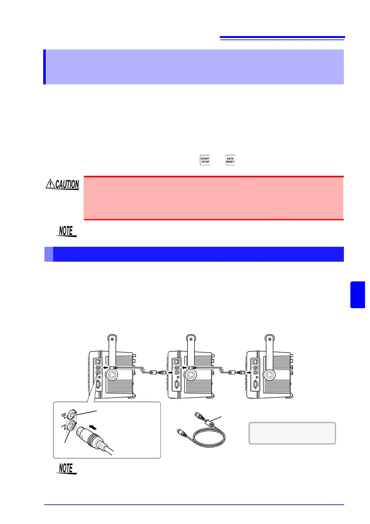
Connecting Multiple 3390 with Sync Cables
Display the MEAS screen on both master and slave units, when executing time control, inte-
gration start/stop, data reset, and HOLDing event.
9683 Connection Cable (for synchronization)
IN
OUT
IN jack
Master Slave 1
Slave 2
Sync interface OUT jack
Ferrite core
Procedure
1. Verify that all 3390s are turned off.
2. As shown below, connect the sync cables between the OUT and IN terminals of the master
and each slave.
3. Turn each instrument on in the following order: master, slave 1, slave 2 (turn the instru-
ments off in the reverse order).
See (p. 131) for sync cable con-
nectors and pin-outs.
• As a single measurement system, settings are made only on the master.
• During synchronous control, the 9683 Connection Cable conduct control signals. Never dis-
connect a sync cable during synchronous control, as the control signals would be interrupted.
• The IN and OUT ends of the 9683 Connection Cable are different. Do not apply excessive insertion force.
• Turning slaves on first may result in synchronization errors.