8.4 Using Analog and Waveform D/A Output Options (must be factory installed before
137
8
Chapter 8 Connecting External Devices
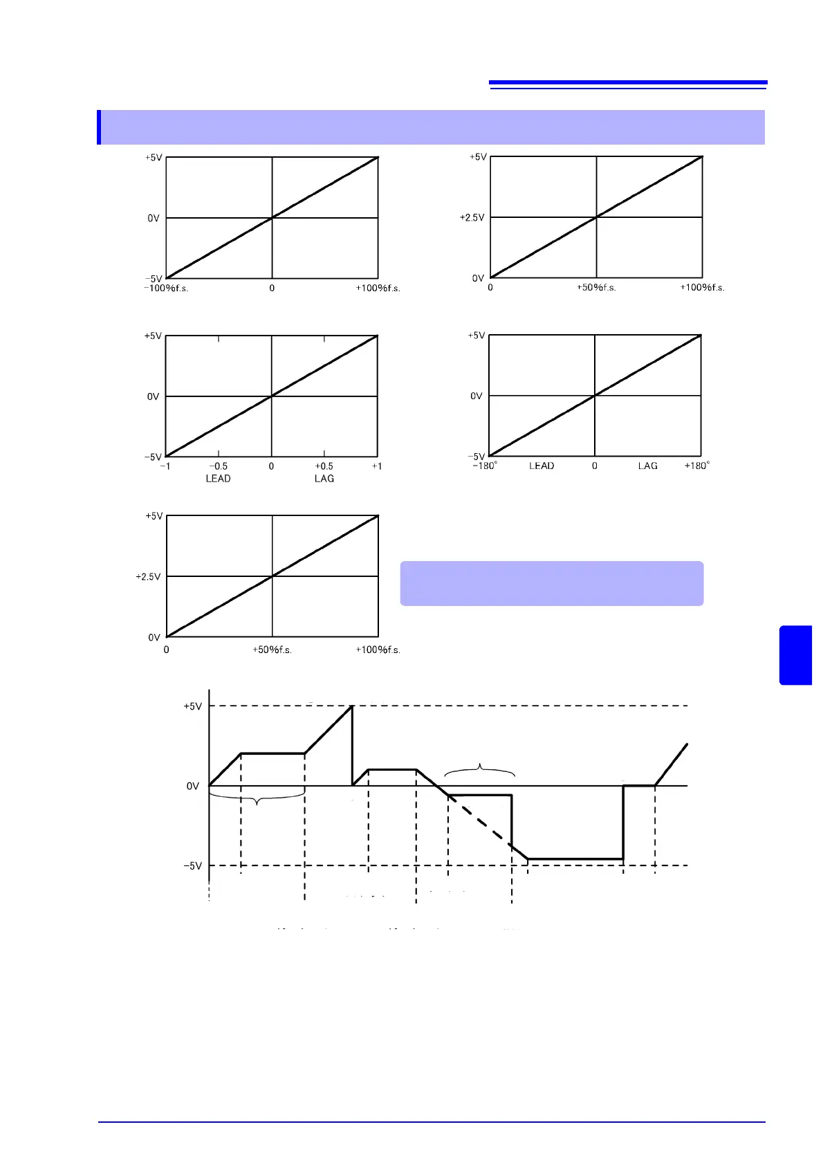
1. Analog output of the integration value is 5 V, which is the product of measurement range × full-scale
integration.
For example, when full-scale integration is set to 10 with the 300 W range, 3 kWh (300W ×10), 6 kWh
(300W × 10 × 2), and 9 kWh (300 W × 10 × 3) are all output as 5 V. (Multiples of -3 kWh are -5 V.)
2. Analog output changes when integration starts, and is held constant after integration stops.
3. The integration value is reset, and analog output becomes 0 V.
4. When the integration value exceeds
±5 V, analog output becomes 0 V and changes proceed from there.
5. When the data hold is activated during integration, analog output is held constant. However, when data
hold is canceled, analog output returns to the actual integration value.
8.4.4 D/A Output Examples
Voltage and current (dc, pk+, pk-),
active power, reactive power
Voltage and current (rms, mn, ac, fnd, thd),
apparent power
Power factor
Power phase angle
Frequency
Output is zero volts (0.0000 Hz displayed) for fre-
quencies below 0.5 Hz and above 5 kHz
Current and Active Power Integration
1. Range × full-scale integration
2.
4.
5.
3.
Output held constant
Output held constant
Output held constant
Time
Stop Integration
Stop Integration
Stop Integration Integration
Reset
Data Hold
Start Integration Resume Integration Resume Integration Data Hold
Cancel
Start Integration
Data
Hold