4.8 Viewing Motor Measurement Values (With Hioki 9791 or 9793 installed)
89
4
Chapter 4 Viewing Measurement Values
If the [Harm sync src] is set to [Ext] when pulses are input to CH B for the rotation signal, voltage and
current phase shift based on the pulses can be seen.
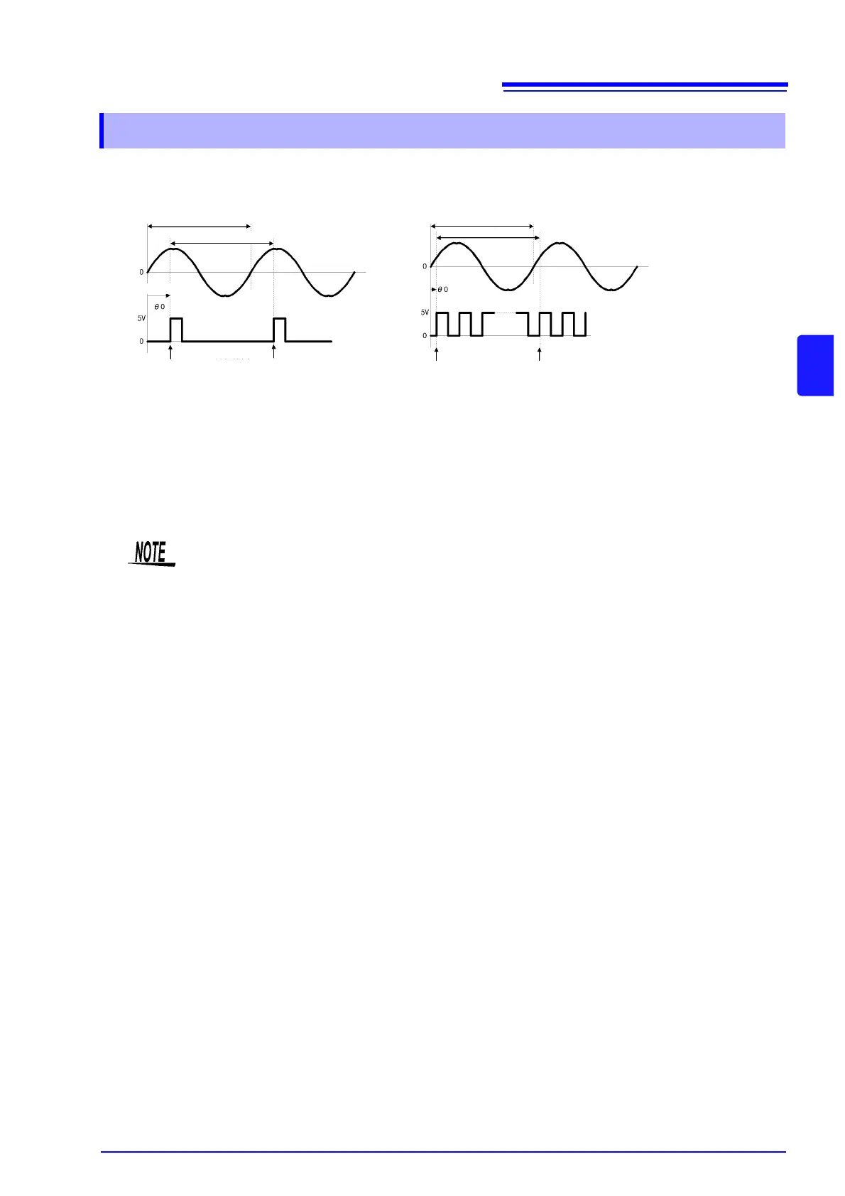
Measuring Electrical Angle with Multiple Pulses
• Use of the original signal (Z phase) is recommended. The original (CH Z) signal serves as a reference
pulse for consistent phase measurements.
• When multiple pulses are used as the rotation signal input without the original (CH Z) signal, the refer-
ence pulse is determined upon synchronization, so upon resynchronization after sync unlock occurs, a
different pulse may become the reference standard.
4.8.2 Measuring Motor Electrical Angle
Single Pulses Multiple Pulses
Fundamental Frequency(U1)
Calculation Range
Calculation Range
Fundamental Frequency(U1)
External Sync Signal
External Sync Signal
Reference
Reference Reference Reference
Phase difference
• Harmonic analysis by synchronization with the rotation signal input pulse requires that the
pulse count be an integer multiple of the input frequency. For example, a 4-pole motor
requires a pulse count that is an integer multiple of two, and a 6-pole motor requires a pulse
count that is an integer multiple of three.
• When a motor with wye internal wiring is measured as a 3P3W3M wiring system, the voltage
and current phase angles can be measured using the
Δ-Y conversion function.