3.10 Attaching to the Lines to be Measured and Zero Adjustment
34
Be sure to read the “"Usage Notes" (p. 5) before attaching to the lines.
Always perform zero adjustment before attaching to the lines.
Then attach the voltage measurement clips and current sensors to the measurement lines according to
the on-screen wiring diagrams. For proper accuracy, attach to the lines exactly as shown.*
* The diagram appears when the wiring mode is selected.(p. 30)
To obtain the specified accuracy, after 30 minutes warm-up, perform zero-adjustment on both voltage
and current measurement channels.
When using an AC/DC current sensor, perform degaussing (DMAG) along with zero adjustment.
3.10 Attaching to the Lines to be Measured
and Zero Adjustment
Although the instrument can measure multiple lines at the same time, to avoid
electric shock and short-circuit accidents, do not attach any unnecessary
cables.
The phases are named A, B, and C on the wiring diagram display. Substitute with
equivalent names such as R,S, and T or U,V, and W, as appropriate.
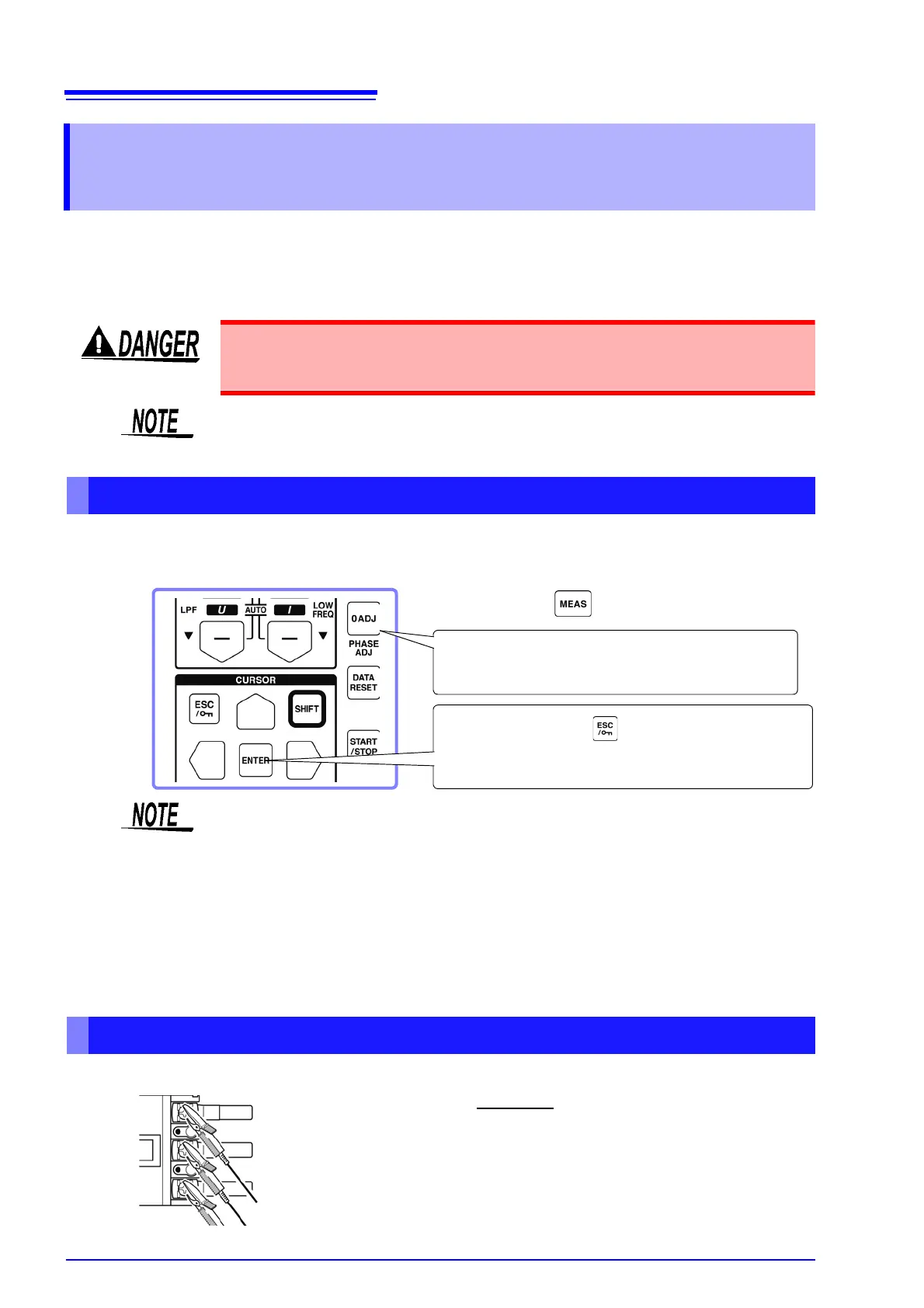
Zero Adjustment and Degaussing (DMAG)
3. Press the key.( to cancel.)
[Executing zero adjustment] is displayed for 30
seconds, until finished.
2. Press the key.
[Execute Zero Adjust.] is displayed.
1. Press the key.
• Perform zero adjustment only after plugging the current sensor into the instru-
ment (proper adjustment requires that the current sensor be connected).
• Perform zero adjustment before attaching to the lines to be measured (proper
adjustment requires the absence of any input voltage or current).
• For optimum measurement accuracy, zero adjustment should be performed
within the specified ambient temperature range.
• The operating keys are disabled during zero adjustment.
• When using a motor evaluation option, zero adjustment is not applicable for
analog DC input on channels A and B. Perform the special zero adjustment
from the Motor screen.
See"4.8 Viewing Motor Measurement Values (With Hioki 9791 or 9793 installed)" (p. 82)
Attach voltage measurement cables to measurement lines
Securely clip the leads to metal parts such as load-side screw terminals or
bus bars.
Example:
Secondary side of breaker
L9438-50 Voltage Cord