3.10 Attaching to the Lines to be Measured and Zero Adjustment
35
3
Chapter 3 Measurement Preparations
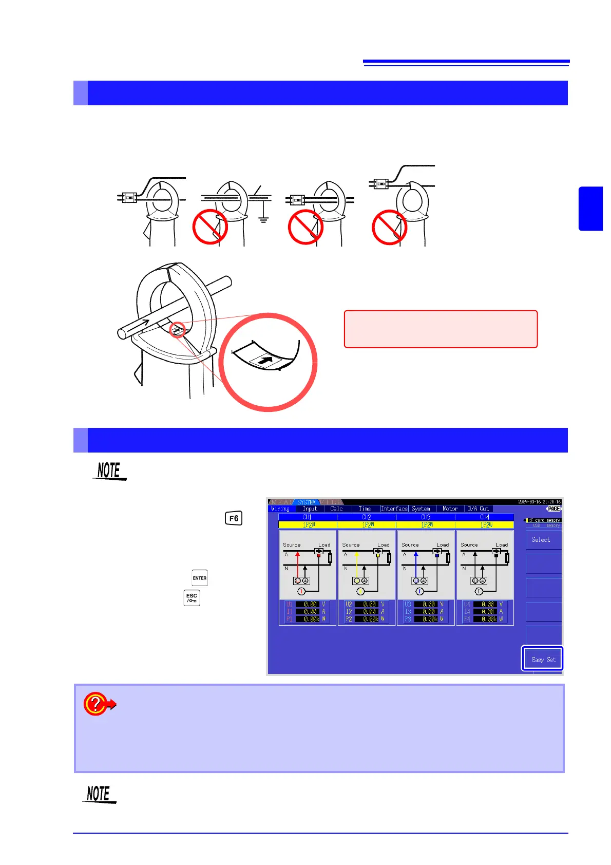
Attach current sensors to measurement lines
OK
Shield
(Example: 9272-10)
Source
side
Line
Load side
Current Flow
Direction Arrow
Be sure to attach each clamp around only one conductor.
Correct measurement cannot be obtained if a clamp is attached around more than one conductor.
Make certain that the current flow direction
arrow points toward the load.
Easy set
If measurement line power is off, turn it on before performing quick setup.
Select [Easy Set] with the key.
A confirmation dialog box appears.
2
1
1
To execute: Press
To cancel: press .
What settings are affected by quick setup?
For accurate measurements, settings such as range and sync source must be properly config-
ured. Executing quick setup automatically configures the following settings to the Hioki-recom-
mended values for the selected wiring mode (phase system): voltage and current ranges, sync
source, lower measurement frequency limit, integration mode, harmonic sync source and rectifi-
cation system.
Execute quick setup when using the instrument the first time, and when changing to a different
line configuration.