3.11 Verifying Correct Wiring (Connection Check)
36
Correct attachment to the lines is necessary for accurate measurements.
Refer to the measured values and vector displays to verify that the measurement cables are correctly attached.
3.11 Verifying Correct Wiring
(Connection Check)
Voltage Current
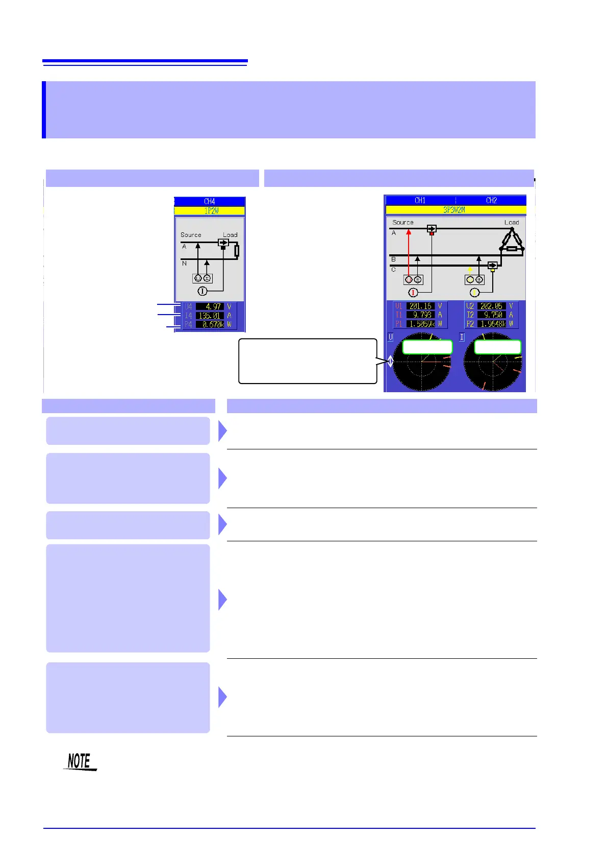
For 1P2W systems For systems other than 1P2W
• Verify that an appropri-
ate measurement
value is displayed.
• Verify that the vectors
are displayed with the
appropriate range.
Measured voltage value
Measured current value
Measured active power value
Verify that an appropriate
measurement value is dis-
played.
Vector line range
Colors match the correspond-
ing lines in the wiring diagram.
In this case Check
• Are the cables securely plugged into the voltage measurement jacks on
the instrument? (p. 28)
• Are the voltage measurement cables properly attached to the lines? (p. 34)
• Are the cables securely plugged into the current measurement jacks on
the instrument? (p. 28)
• Are the current sensors properly attached to the lines? (p. 35)
• Are the current sensors appropriate for the line current to be measured?
• If using the 9272-10 Clamp Sensor, is the sensor range set correctly?
• Are the voltage measurement cables properly attached to the lines? (p. 34)
• Is the arrow marker on the current sensors pointing toward the load? (p. 35)
Voltage vectors:
• Are the cables securely plugged into voltage measurement jacks on the
instrument?(p. 28)
• Are the voltage measurement cable clips properly attached to the lines? (p. 34)
Current vectors:
• Are the cables securely plugged into the current measurement jacks on
the instrument? (p. 28)
• Are the current sensors properly attached to the lines? (p. 35)
• Are the current sensors appropriate for the line current to be measured?
• If using the 9272-10 Clamp Sensor, is the sensor range set correctly?
Voltage vectors:
• Check that the voltage measurement clips are attached to the lines
according to the wiring diagram.
Current vectors:
• Check that the current sensors are attached to the lines according to the
wiring diagram.
If the measured voltage value is
too high or too low
If the measured current value is
not correct
If the measured active power
value is negative
If vectors are too short, or
unequal
If vector direction (phase) or
color is incorrect
• The display range of the vector diagrams assumes inductive loads (such as with a motor).
The vectors may appear out of range when measuring near-zero power factor, or capacitive loads.
• When measuring multiple 1P3W or 3-phase lines at the same time, vectors are not displayed cor-
rectly when the harmonic sync source frequency is different from that of the lines to be measured.
• When measuring 3P3W2M systems, the active power (P) measured on each channel may
be negative.