3.6 Connecting the Voltage Measurement Cables
28
Be sure to read the “Usage Notes” (p. 7) before connecting measurement cables.
Plug the voltage measurement cable leads into the voltage measurement jacks on the instrument (the
number of connections depends on the lines to be measured and selected wiring mode).
Be sure to read the "Usage Notes" (p. 5) before connecting measurement cables.
Plug the current sensor cables into the current measurement jacks on the instrument (the number of con-
nections depends on the lines to be measured and selected wiring mode). See the instruction manual
supplied with the current sensor for specification details and usage procedures.
Use an external VT (PT) or CT. By specifying the VT or CT winding ratio on the instrument, the input level
at the primary side can be read directly.
See"4.2.6 Setting Scaling (when using VT(PT) or CT)" (p. 51)
3.6 Connecting the Voltage Measurement
Cables
Connection Procedure
Plug the voltage cables into the appropriate channels’ voltage
measurement jacks.
Insert the plugs into the terminals as far as they will go.
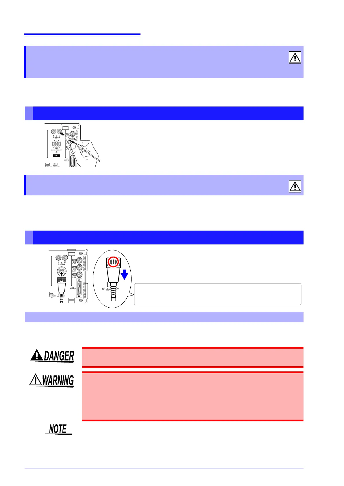
3.7 Connecting the Current Sensors
Connection Procedure
With the arrow on top of the plug, plug each current sensor cable
into the appropriate channel’s current measurement jack.
Insert each plug until you hear it lock.
To disconnect:
Holding the plug around its arrow, slide it forward to unlock, then pull out.
To measure voltage and current beyond the range of the instrument or current sensor
During wiring, avoid touching the VT(PT), CT or input terminals. Exposed live con-
tacts can cause electric shock or other accident resulting in personal injury or death.
• When using an external VT (PT), avoid short-circuiting the secondary winding.
If voltage is applied to the primary when the secondary is shorted, high current
flow in the secondary could burn it out and cause a fire.
• When using an external CT, avoid open-circuiting the secondary winding. If
current flows through the primary when the secondary is open, high voltage
across the secondary could present a dangerous hazard.
• Phase difference in an external VT (PT) or CT can cause power measurement
errors. For optimum power measurement accuracy, use a VT (PT) or CT that exhib-
its minimal phase difference at the operating frequency.
• To ensure safety when using a VT (PT) or CT, one side of the secondary should be
grounded.