8.4 Using Analog and Waveform D/A Output Options (must be factory installed before
132
The instrument can provide analog (p. 135)or waveform output (p. 135) using one of the following D/A
output options (specified before factory shipping).
• 9792 D/A Output Option
• 9793 Motor Testing & D/A Output Option
Both output options provide 16 output channels selectable from the basic measurement items.
Use a mating D-sub connector to connect the D/A outputs to the desired device (oscilloscope, data
logger/recorder).
To be safe, always turn off the instrument and devices before making connections. Turn the instrument
and devices on after confirming the connections.
8.4 Using Analog and Waveform D/A Output
Options (must be factory installed
before shipping)
To avoid electric shock and short circuits, turn the instrument and measurement
line power off before connecting or disconnecting D/A outputs.
• To avoid damage to the instrument, do not short-circuit or apply voltage between outputs.
• The outputs are not isolated from one another.
8.4.1 Connecting Application-Specific Devices to the
Instrument
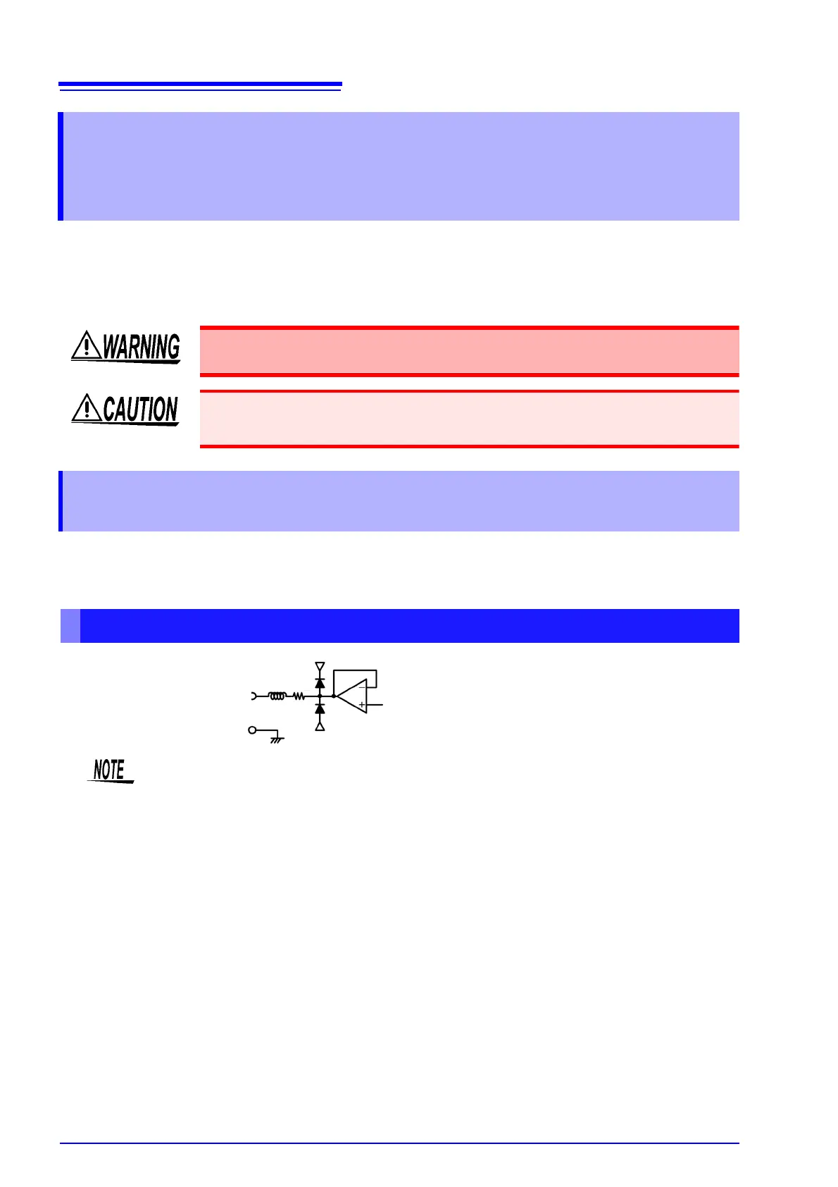
Output Circuit
GND
Output
Terminal
100 Ω
+12 V
-12 V
The impedance of each output is approximately 100 Ω, so the inputs of the recording, DMM or
other device to be connected should be high impedance (at least 1 MΩ).
See "Chapter 10 Specifications" (p. 149)