4.3 Integration Value Observation
56
Select the integration mode for each channel.
Two choices are available for each wiring system.
4.3.2 Setting the Integration Mode
DC Integration
Mode
Integrates instantaneous current and power values for each polarity during every sampling
interval (at 500 kHz sampling frequency)
Only selectable for 1P2W wiring with AC/DC current sensors (Models CT6862, CT6863, 9709,
9277, 9278, and 9279)
Integration is performed simultaneously on three current values (Ih+, Ih-, and Ih) and three
active power values (WP+, WP+, and WP)
RMS Integration
Mode
Integrates RMS current and active power during every measurement interval (50 ms).
Each polarity is integrated only for active power.
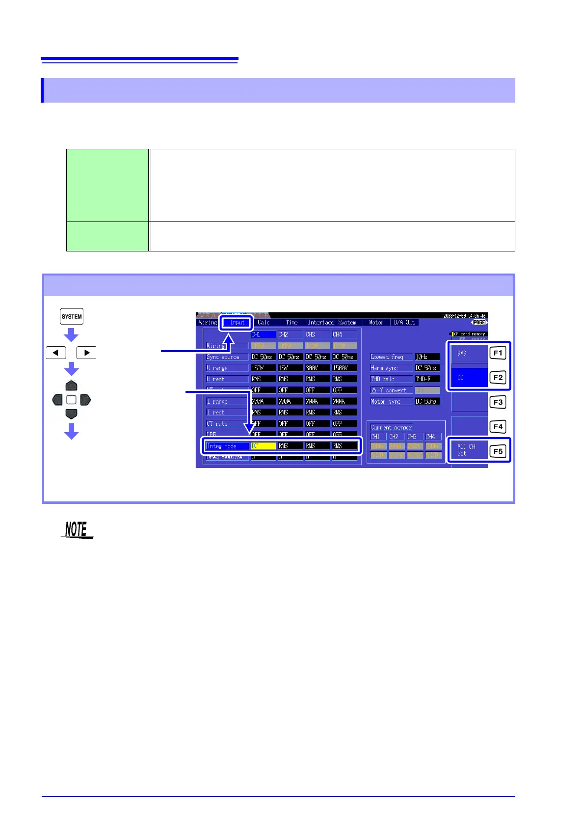
Setting Procedure
Display the
[Input] page
Select with the F keys
Select the channel
to change
See About [All CH Set]. "2.2 Basic Operations" (p. 16)
Display of THD (total harmonic distortion) or RF (ripple factor) of the measurement value is
determined according to the integration mode setting.
When the RMS integration mode is selected, THD is displayed, and when the DC mode is
selected, RF is displayed.