8.4 Using Analog and Waveform D/A Output Options (must be factory installed before
135
8
Chapter 8 Connecting External Devices
• Instrument measurement values are output as level-converted DC voltages.
• Voltage and current (sensor) inputs are isolated from the outputs.
• Select a basic measurement item for each of up to 16 outputs, or for up to eight waveform outputs.
• Long-term trend recording is available by connecting a data logger or recorder.
The full-scale value is set for the analog output in integration.
For example, when the integration value is less than the full scale value, the time for the integration value
to reach full-scale is long, so D/A output voltage changes slowly.
Conversely, when the integration value is larger than the full-scale value, the time to reaching the full-
scale value becomes short, and D/A output voltage changes quickly.
The full scale value of integrated power can be changed for the D/A output by setting the integration full
scale.
• Output signals are waveforms of the instantaneous values of input voltages and currents.
• Voltage inputs and current sensor inputs are mutually isolated.
• Combine with an oscilloscope to observe waveforms of phenomena such as device inrush current.
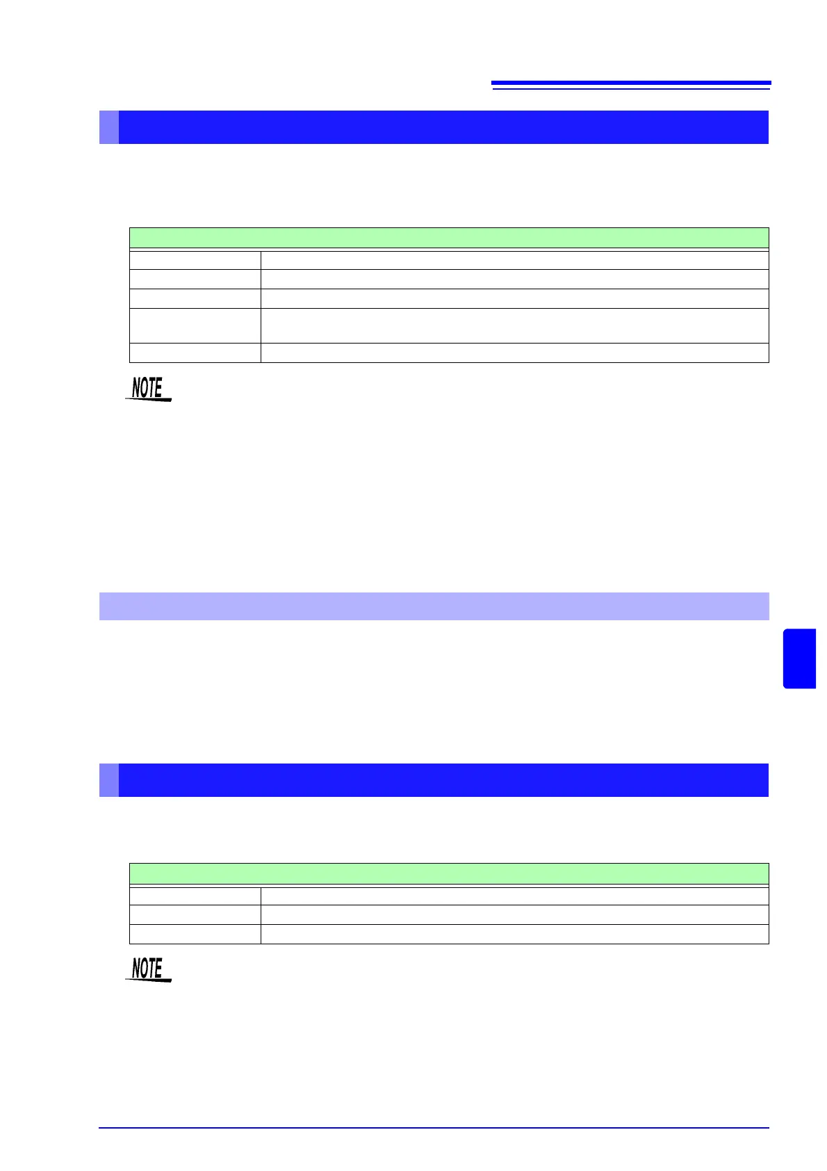
About Analog Outputs
Specifications
Output voltage ±5 V DC (approx. ±12 V max. See "Output Level" (p. 136) for the output ratings of each item)
Output impedance 100 Ω ±5 Ω
Output update rate 50 ms (depending on data update rate of selected item)
Full-scale frequency 100 Hz, 500 Hz, 1 kHz, 5 kHz
(same as the maximum motor measurement frequency setting)
Full-scale integration (1/10, 1/2, 1/1, 5, 10, 50, 100, 500, 1000, 5000, 10000) × range
About Full-Scale Integration
• Positive and negative over-range voltages are approximately +6 and -6 V, respectively. (For voltage
and current peaks are about 5.3 V.)
• Maximum output voltage is approximately ±12 V.
• When using VT or CT ratio, the output is
±5 V DC at the "VT/CT ratio × range".
• When HOLDing, peak HOLDing or averaging, the output value is the result of these func-
tions.
• During data hold when an interval time is set, outputs are updated after each interval.
• When auto-ranging is enabled, the analog output levels change with auto-ranging. Be careful to
avoid range conversion mistakes when measuring rapidly fluctuating values. Such mistakes can be
avoided by using a fixed, manually selected range.
• Harmonic analysis data other than the basic measurement items is not available for output.
About Waveform Outputs
Specifications
Output voltage ±2 V Crest Factor 2.5 or higher
Output impedance 100 Ω ±5 Ω
Output update rate 500 kHz
• D/A1: U1, D/A2: I1, D/A3: U2, D/A4: I2, D/A5: U3, D/A6: I3, D/A7: U4, D/A8: I4
• Waveform clipping occurs at approximately
±7 V.
• Maximum output voltage is approximately
±12 V.
• When using VT or CT ratio, the output is
±2V at "VT/CT ratio × range".
• Waveform output consists of uninterrupted instantaneous values, regardless of data hold, peak
hold, or averaging operations.
• When auto-ranging is enabled, the analog output levels change with auto-ranging. Be careful
to avoid range conversion mistakes when measuring rapidly fluctuating values. Such mis-
takes can be avoided by using a fixed range.