4.2 Viewing Power Measurements, and Changing the Measurement Configuration
48
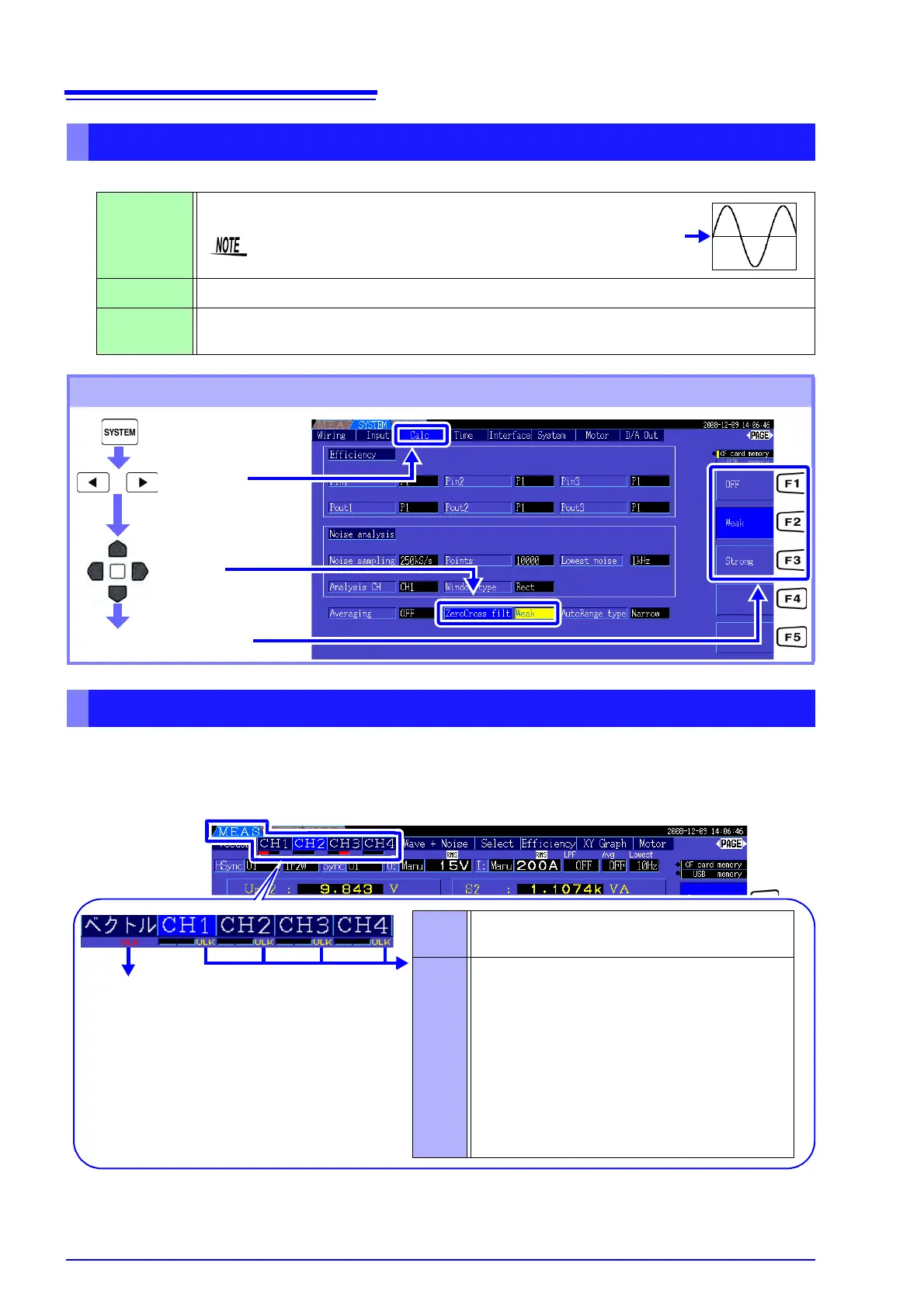
When U or I is selected, set the level of the zero-crossing filter.
When a sync signal cannot be acquired,
* its Sync Unlock indicator appears (see figure below). The indic-
tors for all channels are displayed on all screens, so sync unlock events are visible even when they occur
on channels that are not currently selected for display.
Example. The following case indicates that CH 2 sync is unlocked.
* If the frequency of the selected sync source (input) is not between 0.5 Hz and 5 kHz, or if there is no
sync source input signal, or if the input amplitude is too low (below 30% f.s.)
Setting the Zero-Crossing Filter
OFF
Weak This is the normal (default) setting.
Strong
Select this setting if synchronization is lost because the input fundamental and the carrier frequency
are too close together, such as when measuring an inverter secondary.
Zero-Crossing Filter Setting Procedure
(Ex.)
Set to display waveforms from “0”.
When [OFF] is selected, accuracy is undetermined, so always
select the Weak or Strong setting when viewing measurement values.
0
Display the
[Calc] page
Select with the F keys
Select
[ZeroCross filt]
About the Sync Unlock Indicators
Harmonic sync source unlocked
See "4.4.4 Selecting the Harmonic Sync Source"
(p. 67)
Red Indicates sync is unlocked.
The channel cannot be measured accurately.
Yellow “ULK” lights yellow when the frequency of any
sync source channel is at or below 99% (or at or
above 101%) of the harmonic sync source. In this
case, the harmonics of each measured value, the
fundamental content (Ufnd and Ifnd), and the total
harmonic ripple distortion percentages (Uthd and
Ithd) cannot be measured correctly.
Example. When the frequency of the harmonic
sync source is 50 Hz and the frequency of the sync
source channel is 49.5 Hz or less, or 50.5 Hz or more.
Harmonic sync source unlocked