8.5 Using the Motor Testing Option (when specified before factory shipping, for motor
139
8
Chapter 8 Connecting External Devices
See section "4.8 Viewing Motor Measurement Values (With Hioki 9791 or 9793 installed)" (p. 82) for
measurement displays and instrument setting procedures.
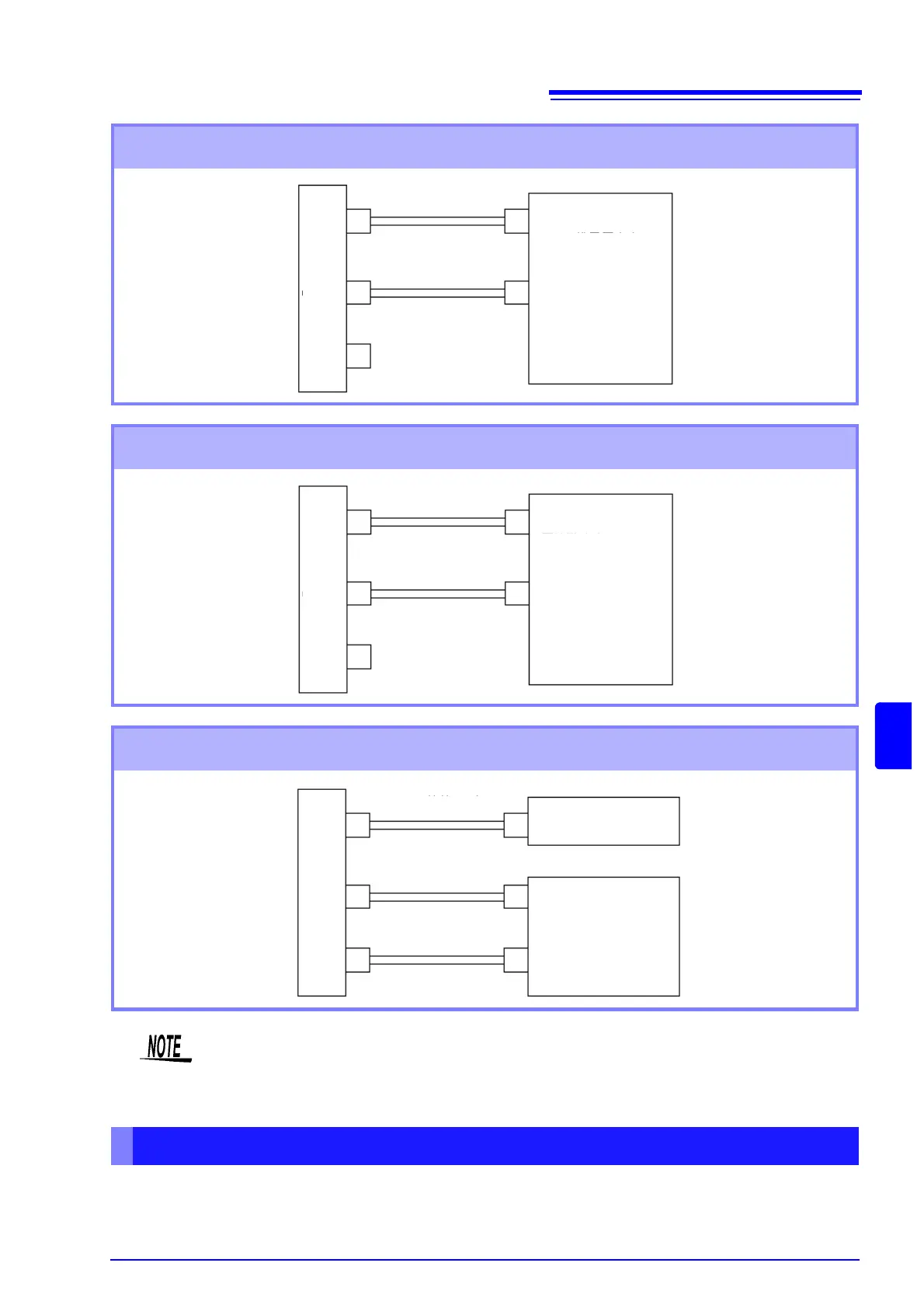
Example 1. Connecting a torque meter that provides analog torque values and
rotation signals
CH A
CH B
CH Z
L9217 Connection Cord
-10 V to 0 V to +10 V
-10 V to 0 V to +10 V
Torque value
Analog voltage output
Rotation signal
Analog voltage output
Torque Meter
Example 2. Connecting a torque meter that provides torque values as frequency
and rotation signals as pulses
Example 3. Connecting a torque meter that provides torque values as frequency
and incremental rotary encoder signals
CH A
CH B
CH Z
L9217 Connection Cord
Torque value
Frequency output
Rotation signal
Pulse output
Torque meter
CH A
CH B
CH Z
L9217 Connection Cord
A-phase pulse output
Z-phase pulse output
Torque value
Frequency output
Incremental Rotary Encoder
Torque meter
Motor Analysis Settings on the Instrument, Displaying Measured Values
• CHPulse measurement is not available with CH Z only. Always use pulse input to CH B in
combination with CH Z.
• When using CH Z (original position signal or Z-phase), apply a train of at least four pulses to CH B.