10.1 General Specifications
154
(3) Pulse Input (CH B only)
Detection level Not more than 0.5 V Low, and at least 2.0 V High
Measurement range 1 Hz to 200 kHz (at 50% duty)
Division setting range 1 to 60000
Measurement frequency range 0.5 Hz to 5.0 kHz (limited to measured pulse frequency divided by selected no. of divisions)
Minimum detectable pulse width 2.5 µs or better
Measurement accuracy ±0.05%rdg. ±3dgt.
(4)Pulse Input (CH Z only)
Detection level Not more than 0.5 V Low, and at least 2.0 V High
Measurement range 0.1 Hz to 1 kHz
Minimum detectable pulse width 2.5 μs or better
Settings OFF/ON (when ON, division of CH B is cleared on rising edges)
7. D/A Output Option Specifications (Models 9792 and 9793)
Number of output channels 16 channels
Output contents Selectable waveform/analog outputs (from basic measurement parameters)
Waveform output only on Channels 1 to 8
Output connector One 25-pin female D-sub
D/A conversion resolution 16 bits (polarity + 15 bits)
Output accuracy Analog output.........Measurement accuracy ±0.2%f.s. (DC level)
Waveform output....Measurement accuracy±0.5%f.s. (rms level within synchronous frequency range)
Output update interval Analog output.........50 ms (according to input data update interval of selected parameter)
Waveform output....500 kHz
Output voltage Analog output......... ±5 V DC nom. (approx. ±12 V DC max.)
Waveform output ...±2 V (crest factor at least 2.5)
Output impedance 100 Ω ±5 Ω
Period of guaranteed accuracy 6 months (1.5 times specified accuracy for one year)
Conditions of Guaranteed Accura-
cy
Temperature and humidity: 23±3°C 80% RH or less
Warm-up time:.................... 30 minutes or more, After zero adjustment of the 3390
Temperature Coefficient ±0.05%f.s./°C
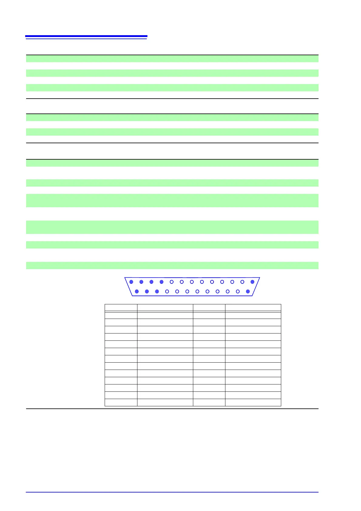
Pinout
13 12 11 10 9 8 7 6 5 4 3 2 1
25 24 23 22 21 20 19 18 17 16 15 14
Pin No. Output (Waveform) Pin No. Output (Waveform)
1GND14GND
2 D/A1 (U1) 15 D/A9
3 D/A2 (I1) 16 D/A10
4 D/A3 (U2) 17 D/A11
5 D/A4 (I2) 18 D/A12
6 D/A5 (U3) 19 D/A13
7 D/A6 (I3) 20 D/A14
8 D/A7 (U4) 21 D/A15
9 D/A8 (I4) 22 D/A16
10 GND 23 GND
11 GND 24 GND
12 GND 25 GND
13 GND - - - - - - - - - - - -