10.5
Calculation Formula Specifications
168
(i) : .......... Measurement channel
M : .......... Number of synchronous samples
s :........... Sample (data point) number
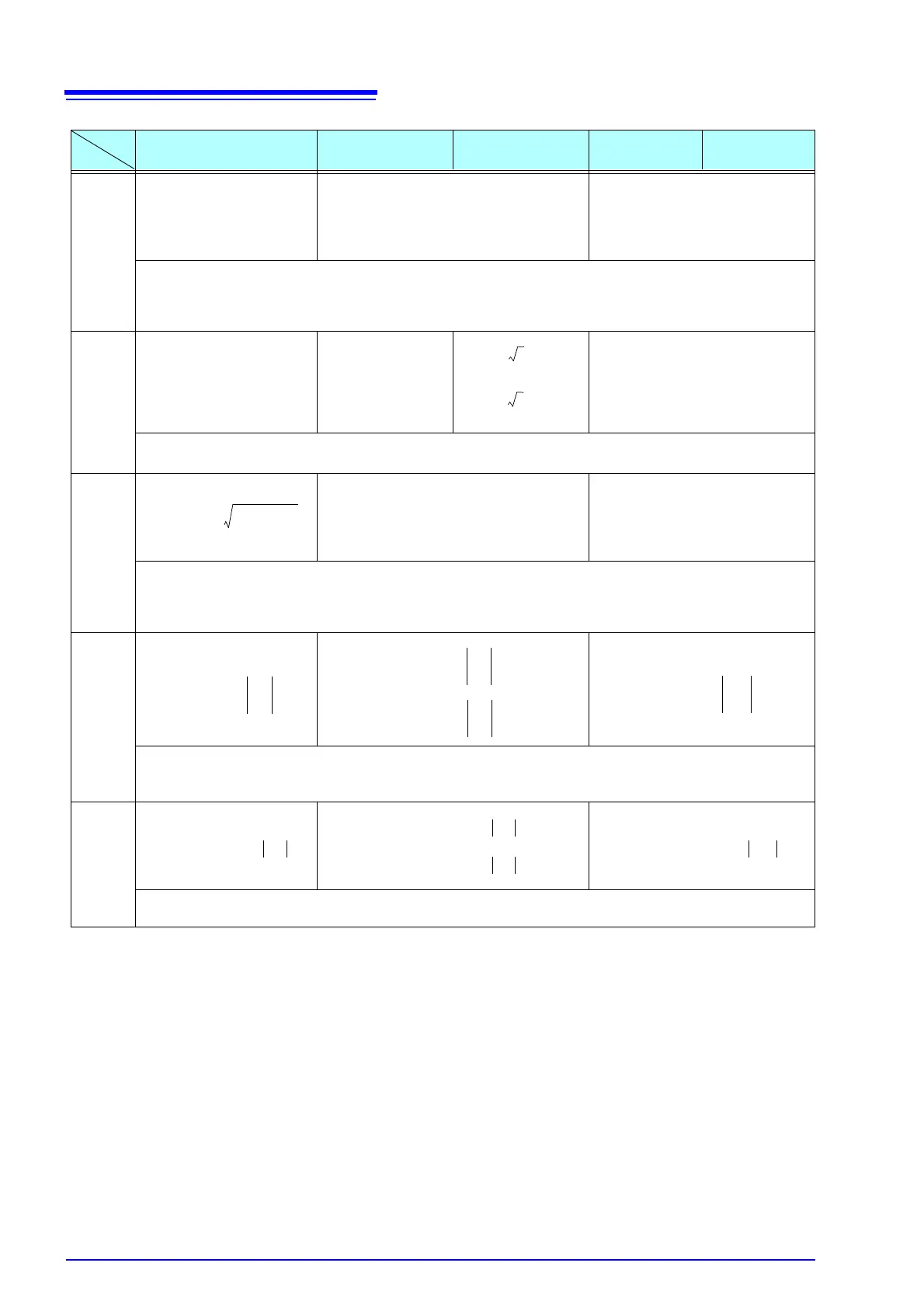
1P2W 1P3W 3P3W2M 3P3W3M 3P4W
Active
power
• For 3P3W3M and 3P4W systems, phase voltage is used for waveform voltage U(i)s.
(3P3W3M:U1s=(U1s-U3s)/3, U2s=(U2s-U1s)/3, U3s=(U3s-U2s)/3)
• The polarity sign for active power indicates power flow direction: positive (+P) for forward power (consumption), and neg-
ative (-P) for reverse power (regeneration), and indicates net current flow for power.
Apparent
power
• Select U(i) and i(i) from rms/mn.
• For 3P3W3M and 3P4W waveforms, U(i) is phase voltage.
Reactive
power
• The polarity sign (si) for reactive power (Q) is indicated by [none] for lag or [–] for lead.
• The polarity sign (si(i)) for each channel (i) is acquired from lag or lead of the voltage waveform U(i)s and current wave-
form I(i)s. For 3P3W3M and 3P4W waveforms, U(i)s is phase voltage.
(3P3W3M:U1s=(U1s-U3s)/3, U2s=(U2s-U1s)/3, U3s=(U3s-U2s)/3)
Power
factor
• The polarity (si) for power factor (
λ
) is indicated by [no sign] for lag or [–] for lead.
• The polarity sign (si(i)) for each channel (i) is acquired from lag or lead of the voltage waveform U(i)s and current wave-
form I(i)s. Polarities si12, si34, and si123 are acquired from reactive power values Q12, Q34, and Q123, respectively.
Power
phase
angle
• The polarity sign (si(i)) for each channel (i) is acquired from lag or lead of the voltage waveform U(i)s and current wave-
form I(i)s. Polarities si12, si34, and si123 are acquired from reactive power values Q12, Q34, and Q123, respectively.
P
i()
1
M
-----
U
i()
sI
i()
s×()
s0=
M1–
=
λ
i() si i()
P i()
S i()
--------
=
λ
123 si
123
P
123
S
123
----------
=