11.2 Trouble Shooting
176
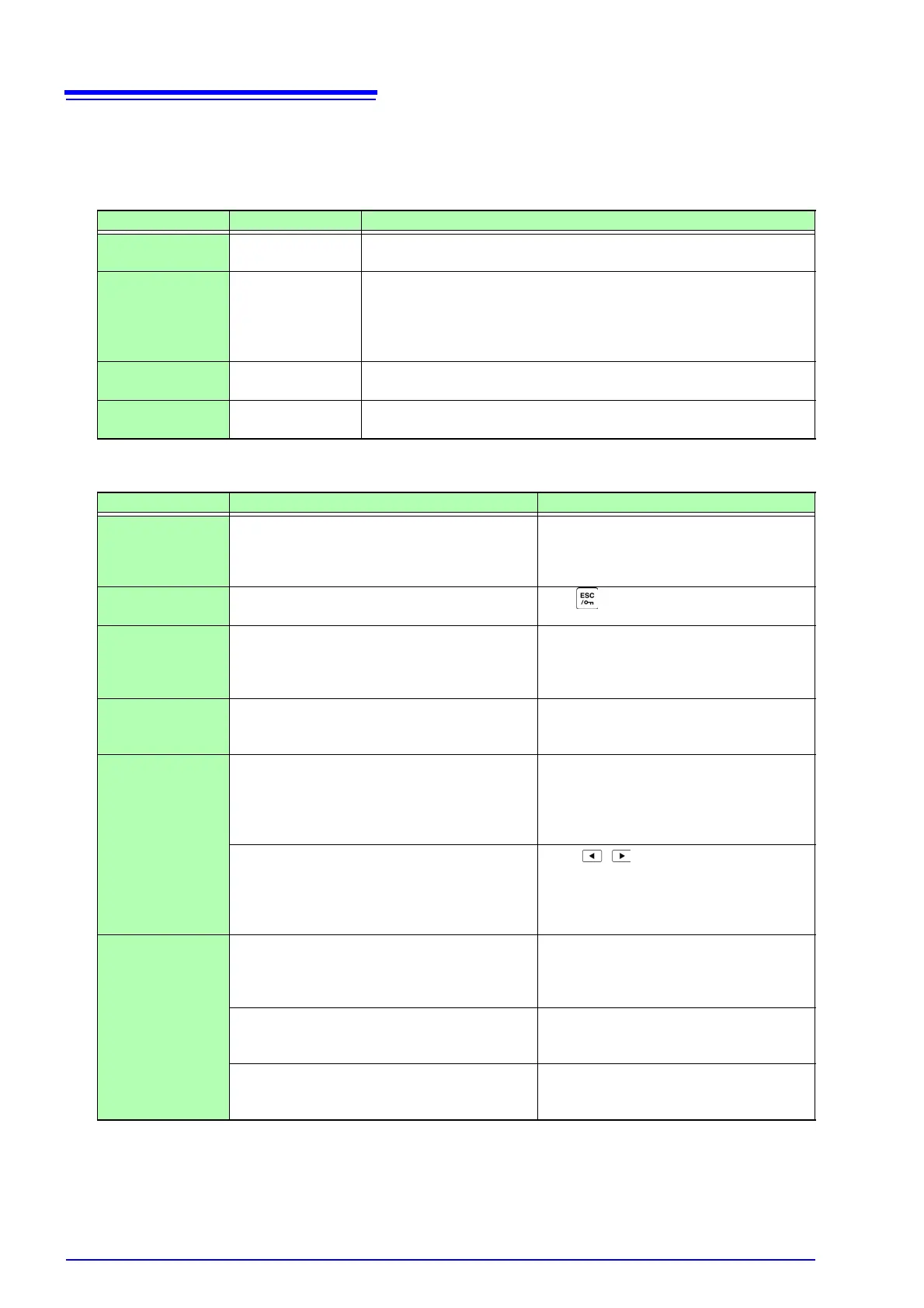
Replaceable Parts and Useful Life
Certain parts require replacement periodically and at the end of their useful life: (Useful life depends on
the operating environment and frequency of use. Operation cannot be guaranteed beyond the following
periods)
Before returning for repair
When no apparent cause can be established
Perform a system reset.
This will return all settings to their factory defaults.
See "6.1 Initializing the Instrument (System Reset)" (p. 101)
Part Useful Life Remarks
Electrolytic
Capacitors
Approx. 10 years
The useful life of electrolytic capacitors depends on the operating envi-
ronment. Periodic replacement is necessary.
Lithium battery Approx. 10 years
The instrument contains a built-in backup lithium battery, which offers a
service life of about ten years. If the date and time deviate substantially
when the instrument is switched on, or backup error is returned in self-
test, it is the time to replace that battery. Contact your dealer or Hioki rep-
resentative.
Fan motor
Approx. 50,000
hours
Periodic replacement is necessary.
LCD backlight
(to half brightness)
Approx. 50,000
hours
Periodic replacement is necessary.
Symptom Check Item, or Cause Remedy and Reference
The display does
not appear when
you turn the power
on.
Is the power cord unplugged?
Is it properly connected?
Confirm that the power cord is properly con-
nected.
See "3.4 Connecting the Power Cord" (p. 27)
Keys do not work. Are the keys locked?
Hold for three seconds to disable the
key-lock function.
Cannot print.
Is the recording paper properly loaded?
Are the printer settings (e.g., communication
speed and interface type) correct? Is the printer
connected properly with the correct cable?
See "8.1 Connecting a Printer (to print cap-
tured screen images)" (p. 123)
The MENU key is
lit, but the screen is
blank
The LCD backlight is set to turn off after a speci-
fied interval.
"LCD back light" (p. 100)
Press any key.
Voltage or current
measurement
values are not
displayed
Are the voltage measurement and current sensor
cables connected properly?
Check connections and wiring.
See "3.6 Connecting the Voltage Measure-
ment Cables" (p. 28), "3.11 Verifying
Correct Wiring (Connection Check)"
(p. 36)
Is the proper input channel displayed (e.g., when
measuring input on CH1, is the
[CH1] page dis-
played)?
Press to change the input channel
page.
See "4.2 Viewing Power Measurements,
and Changing the Measurement Con-
figuration" (p. 41)
Frequency mea-
surement is impos-
sible, measured
values are unstable
Is the input frequency within the range 0.5 Hz to 5
kHz?
Verify the input frequency using the noise
measurement function.
See "4.6 Viewing Noise Measurement Val-
ues (FFT Function)" (p. 72)
Is the input frequency below the lower limit set-
ting?
Set the lower limit frequency for measure-
ment.
See "4.2.3 Selecting the Sync Source" (p. 47)
Is the sync source input correct?
Is the range of the sync source input too high?
Check the sync source settings.
See "4.2.3 Selecting the Sync Source" (p. 47),
"4.2.2 Selecting Ranges" (p. 43)