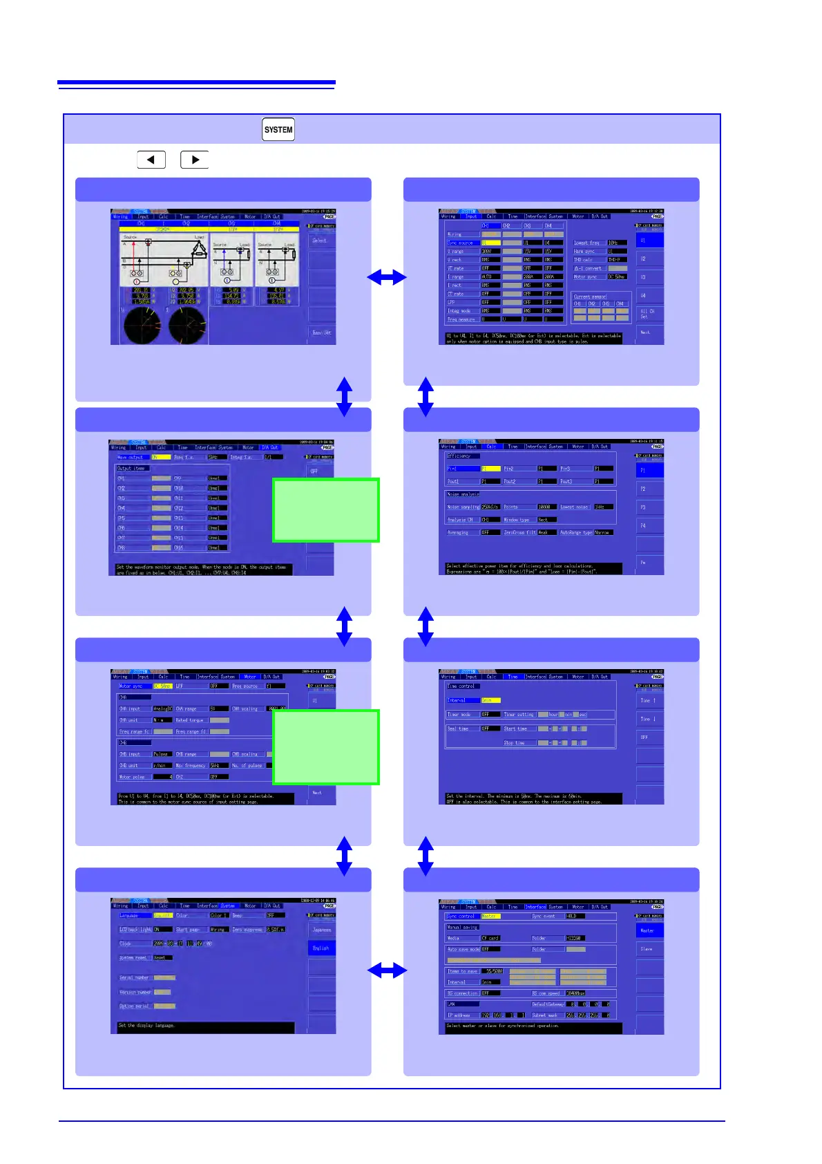
[Motor]
[Wiring]
[D/A Out]
[System]
Select the appropriate wiring mode (phase system configu-
rations) and execute quick setup on this page. Wiring dia-
grams for each mode depict the appropriate
measurement cable connections.
Make D/A output-related settings on this page.
Make motor measurement-related settings
on this page.
Configure system environment settings and
perform system reset on this page.
[Input]
Make detailed measurement criteria settings on
this page.
[Calc]
Make calculation-related settings on this page.
[Time]
Set measurement timers and the number of pa-
rameters to save on this page.
[Interface]
Make settings related to synchronization, data
saving and interfaces on this page.
Setting Screen (Press the key to display)
Press the keys to change the screen page as follows.
Use this screen to view and change settings for measurement criteria,
wiring mode, wiring check and system environment configuration.
Appears only when
the Model 9791 Mo-
tor Testing option or
the 9793 Motor Test-
ing & D/A Output op-
tion is installed.
9792 D/A Output op-
tion or the 9793 Mo-
tor Testing & D/A
Output option is in-
stalled.