EasyManuals Logo

Honeywell touchpoint Pro Technical Handbook

Honeywell touchpoint Pro
200 pages
To Next Page IconTo Next Page
To Previous Page IconTo Previous Page
Page #104 background imageLoading...
Page #104 background image
CONFIGURATION
Part. No. 2400M2501_6 Touchpoint Pro
97 Technical Handbook
Rate
Alarm
Summary
LTEL Alarm
Summary
STEL
Alarm
Summary
Alarm 3
Summary
Alarm 2
Summary
Alarm 1
Summary
Inhibit
Summary
Fault
Summary
Not
Used
Not
Used
Not
Used
Not
Used
Not
Used
Not
Used
Not
Used
Not
Used
System
Summary
11025
11026
11027
11028
11029
11030
11031
11032
11033
11034
11035
11036
11037
11038
11039
11040
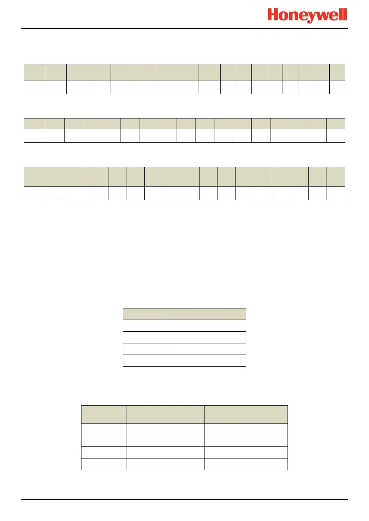
Table 20. Modbus System Summary
Not Used
Not Used
Not Used
Not Used
Not Used
Not Used
Not Used
Not Used
Not Used
Not Used
Not Used
Not Used
Not Used
Not Used
Not Used
Not Used
System
Summary
11041
11042
11043
11044
11045
11046
11047
11048
11049
11050
11051
11052
11053
11054
11055
11056
Table 21. Modbus System Summary Continued
Safe State
Summary
(Future
Use)
Warning
Summary
Not
Used
Not
Used
Not
Used
Not
Used
Not
Used
Not
Used
Not
Used
Not
Used
Not
Used
Not
Used
Not
Used
Not
Used
Not
Used
Not
Used
System
Summary
11057
11058
11059
11060
11061
11062
11063
11064
11065
11066
11067
11068
11069
11070
11071
11072
Table 22. Modbus System Summary Continued
11.2 Modbus Register Allocation for Function 04 Read Input Registers
There are three sets of input registers for each channel:
1. The analogue signal expressed as a 16 bit signed integer value.
2. The analogue signal expressed as a 32 bit floating point value.
3. An animation value.
11.2.1 Analogue Registers (Integer)
This register contains the indicated measured value in steps of 0.1 measurement units (e.g. PPM, LEL). This register should
not be used on channels where the parameter "Gas Range Max" is set to values greater than 1000.
Channel
Analogue Value (Integer)
01
30001
02
30002
64
30064
Table 23. Modbus Channel Analogue Values
Note: The Integer format is a 16 bit signed integer.
11.2.2 Analogue Registers (Float)
Channel
Analogue Value (Float)
Register 1
Analogue Value (Float)
Register 2
01
30129
30130
02
30131
30132
64
30255
30256
Table 24. Modbus Channel Analogue Values (Float)
Note: The Float format is a 32 bit floating point value in accordance with IEEE 754-2008.

Table of Contents

Other manuals for Honeywell touchpoint Pro

Questions and Answers:

Question and Answer IconNeed help?

Do you have a question about the Honeywell touchpoint Pro and is the answer not in the manual?

Honeywell touchpoint Pro Specifications

General IconGeneral
BrandHoneywell
Modeltouchpoint Pro
CategoryControl Systems
LanguageEnglish

Related product manuals