MODBUS INSTALLATION
Part. No. 2400M2501_6 Touchpoint Pro
47 Technical Handbook
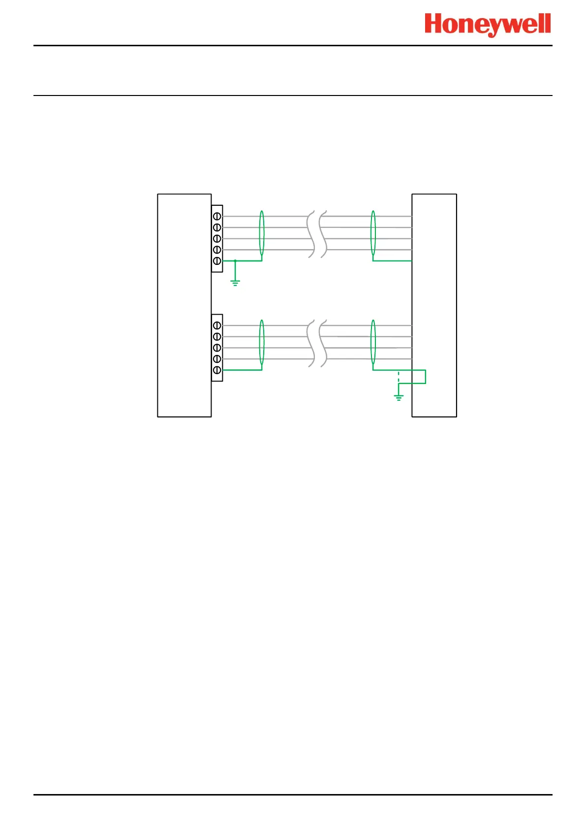
5.3.1.2 Screen Connections
It is the installer’s responsibility to provide suitable connections for ring cable screens.
The Drain (DRN) connections at the controller and at the RCM should be connected. They are capacitively coupled to the
controller/backplane 24V return (0V) line, and isolated to DC.
Connections to earth or chassis must be made externally.
Figure 62. Representative Screen Connections
5.3.1.3 Earth Clamp
The ring cable screen should be connected to chassis using a suitable clamp. To avoid ground loops, each screen should
only be grounded at one end.
5.3.1.4 Multiple RCMs
Screens between multiple RCMs may be connected using the RCM DRN connections on pin 2/5 and 8/11. Each leg should
be provided with a separate single earth connection.
5.3.1.5 Communications Ring Cabling
The communications ring uses RS485 signalling.
The external ring network cabling should use 2x2 twisted pair cables with overall screen. The cable used should take into
account the location, environment and distance but must be a good quality signal cable suitable for RS485 signals and
meeting the following requirements:
Mutual capacitance conductor to conductor
Mutual capacitance conductor to shield
Inductance conductor to shield
Table 14. Communications Ring Cable
For ease of wiring and commissioning, different wiring colours should be used for A and B rings. The terminals will accept a
maximum wire size of 1.5 mm² / AWG 15.
RCMController
1
3
4
2
TB2
5
Pin 2 or 5
1
3
4
2
TB3
5
Pins 8, 11
Local Remote
DRN
DRN

 Loading...


