INTRODUCTION
Part. No. 2400M2501_6 Touchpoint Pro
22 Technical Handbook
3.4.3 DC Uninterruptible Power Supply (DC-UPS) Module
The DC-UPS Module can be used with the separate and optional TPPR Battery Enclosure to provide continuous and
uninterrupted power to the TPPR in the event of an external power failure.
The DC-UPS is adjustable for buffer time and buffer voltage, and carries red, yellow and green status LEDs and descriptions
that show your backup battery status (see tables below).
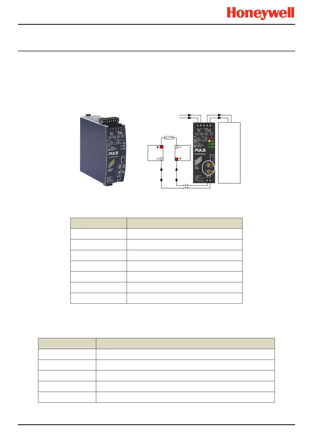
Note: The DC-UPS Module Buffer Voltage should be set at 26 VDC to ensure optimum battery charging, and the Buffer-time
Limiter should usually be set to ∞ (see circled area on the figure below).
Figure 29. DC-UPS and Battery Configuration
The DC-UPS terminals are as follows:
–24 VDC input from UPS (spare)
+24 VDC output to 20 A (max) Load
–24 VDC output to 20 A (max) Load
Table 4. DC-UPS Primary Terminal Allocation
The DC-UPS also has Normally Open (NO) relay terminals that can be used for external repeaters such as a lamp stack or
alarm buzzer, as shown in the table below:
Ready relay: Closed when all is Ok (green)
Buffering relay: Closed when batteries are supplying power (yellow or buzzer)
Replace Battery relay: Closed when batteries fail load test (red or buzzer)
Do not use as Inhibit belongs to the Controller only
Table 5. DC-UPS Secondary Terminal Allocation
20 A max
Load
12 VDC
Battery
12 VDC
Battery
24 VDC 24 VDC

 Loading...


