INTRODUCTION
Part. No. 2400M2501_6 Touchpoint Pro
14 Technical Handbook
3.3 TPPR System Key Components
3.3.1 Enclosures and Racks
TPPR can be mounted in various sizes of floor or wall mounted enclosures, or on 19” 5U racks. The floor mounted
enclosures can be unventilated, naturally ventilated, or force ventilated. The fully sealed wall mounted enclosures can hold a
controller or can be a remote terminal without a controller.
If using a 19” rack, the OEM or installer must ensure the installation is at least IP20 / Type 1 / Class 1 (grounded) to mitigate
the risk of electrical shock.
Figure 18. TPPR Enclosures
3.3.2 TPPR Controller User Interfaces
The TPPR Controller is covered with a protective membrane and houses the touch screen user interface (UI), the alarm
buzzer, the Accept and Reset buttons, and coloured LEDs for Power, Alarm, Fault, and Inhibit.
The controller has four access methods:
Control Panel touch screen for normal system operation, maintenance and configuration
PC Configuration Software (optional licences) for secure maintenance and configuration over a VPN or cable
Webserver (optional licences) allows up to 5 people to securely view events and carry out basic system operation via
an Ethernet connection or the Internet
Modbus option
Internal System Interfaces consist of:
Two master relays that signal System Failure and System Fault
Connections for one SD Card and one USB drive
10/100 Mbps Ethernet connection (for networked interfacing)
Optional dual RS 485 Modbus RTU interface
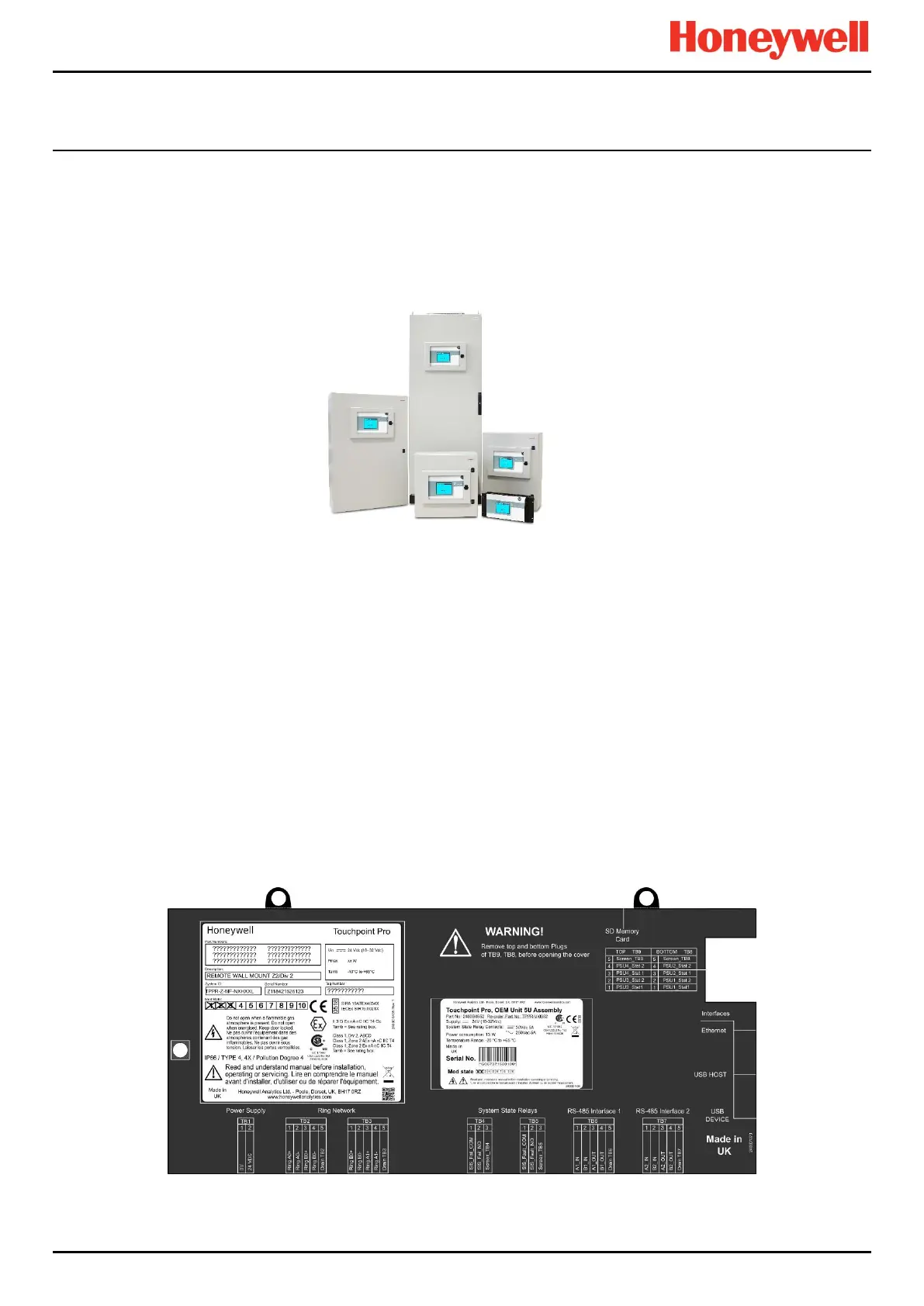
Figure 19. TPPR Controller Cover with Connection Map

 Loading...


