MODBUS INSTALLATION
Part. No. 2400M2501_6 Touchpoint Pro
40 Technical Handbook
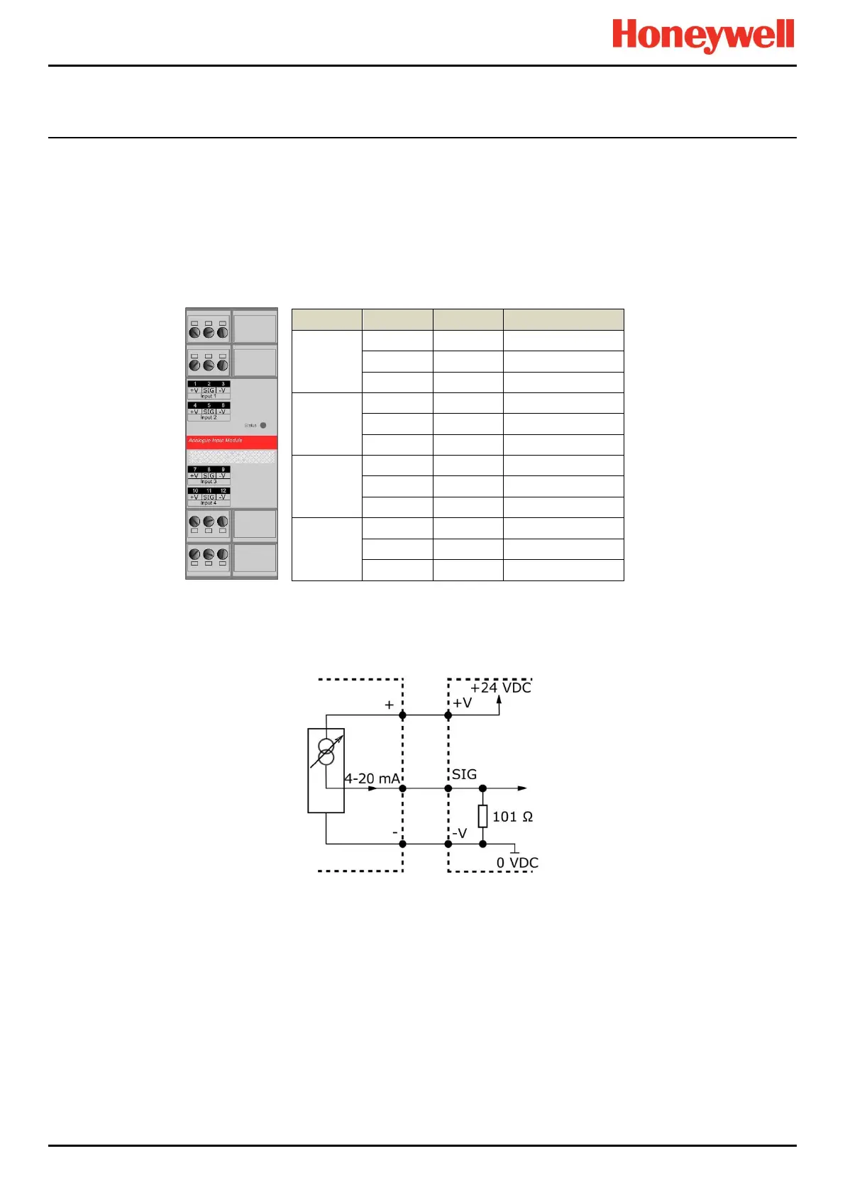
5.2.14 Connecting to an Analogue Input Module (4 – 20 mA)
The Analogue Input Module mA (AIM mA) is a sink module that accepts 4-20 mA source signals from 2-wire or 3-wire field
devices. The sensors connect via the front-face terminals.
The module can supply 18-32 VDC (24 VDC nominal) to the field devices at a maximum current of 1 A per channel, with the
additional limitation that the total current drawn from the module must not exceed 2 A at 65 °C ambient or 4 A at 55 °C
ambient.
Voltage outputs are overload protected.
Table 9. AIM mA Connection Table
The following diagrams show how to connect various types of device or sensor.
Figure 49. Three Wire Device

 Loading...


