MAINTENANCE
Part. No. 2400M2501_6 Touchpoint Pro
141 Technical Handbook
16.12 How to Check the DC-UPS
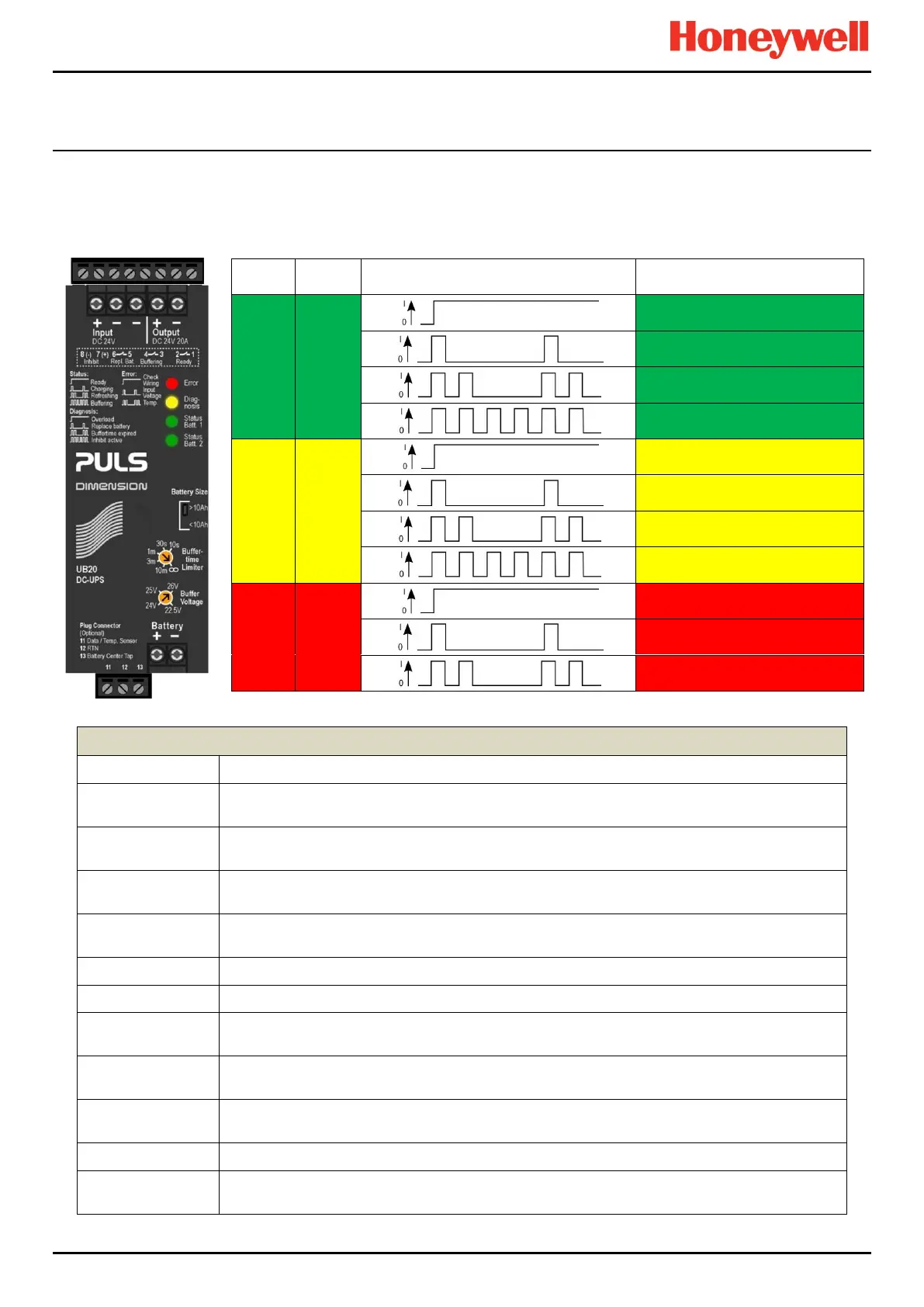
The DC-UPS module has a range of LEDs that indicate UPS system states, as listed both on the DC-UPS module cover,
and in the table below. These LEDs should be checked regularly and before isolating the battery or mains power supplies.
Note: TPPR batteries are replaced as a pair, ‘Battery Centre Tap’ is not used, and individual battery status is not shown.
Check Temperature (Unused)
Figure 97. DC-UPS Signal Key
Sets the charging current, This should be set to >10 Ah, which gives a charging current of 3.0 A.
The input voltage is below the transfer threshold level, and the TPPR is running on battery power
(buffering). See Buffertime below.
A DC-UPS supplying nominal DC 24 V @ 20A should provide power for ≈ 15 or 30 minutes with 12
Ah and 27 Ah batteries respectively. Normally set to infinite.
The battery output time has exceeded the setting on the Buffertime limiter, or buffering has been
stopped to protect the batteries. This signal displays for 15 minutes only.
Sets how long the UPS will supply power. Usually set to infinity (∞), which allows the system to run
until power is restored or until the batteries discharge below safe working limits.
Sets the nominal charging power. Normally set to 24V. (PSUs are set to 26V to allow charging.).
The battery capacity is below 85 % and the batteries are charging.
Indicates that buffering ability is disabled (charging of batteries will continue) or that a buffering
event was aborted due to the inhibit function.
Input voltage is lower than the selected Buffer voltage + 1.0 V, or higher than the input over-voltage
protection (OVP) level.
Indicates if the output current is higher than specified values or that the DC-UPS has shut down
during hiccup mode.
The battery charge is above 85 % and no faults are detected.
Indicates that the batteries have failed the battery health check and should be replaced as soon as
possible.

 Loading...


