MODBUS INSTALLATION
Part. No. 2400M2501_6 Touchpoint Pro
45 Technical Handbook
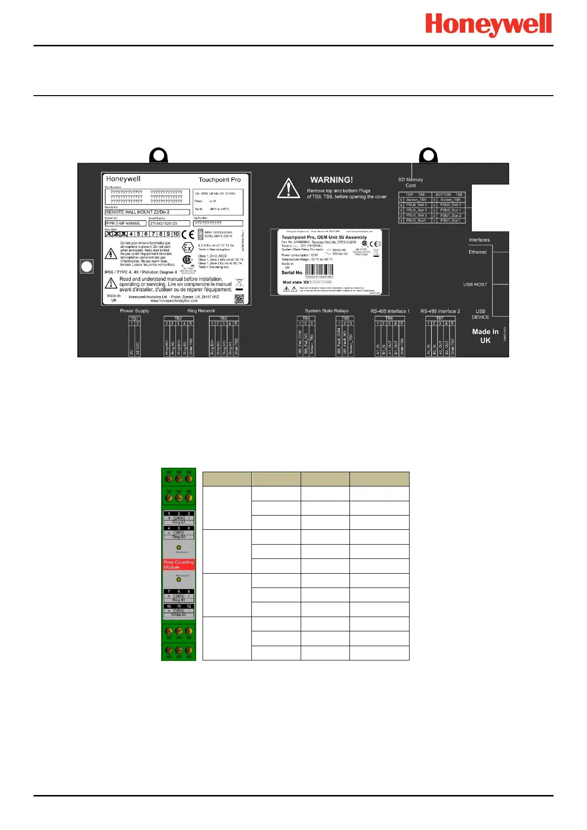
5.3 Controller Electrical Connections
Controller electrical connections are detailed on the Controller cover (shown below).
Figure 59. Controller’s Terminal Layout Map
5.3.1 Communications Ring Wiring
The ring wiring connects from TB2 and TB3 on the controller to one or more Ring Coupling Modules (RCMs), depending on
the system configuration. The RCMs may be fitted in the same cabinet as the controller, in a remote cabinet up to 1km
away, or a combination.
5.3.1.1 Ring Coupling Module (RCM) Connections
Each backplane requires an RCM. The RCM is normally positioned in the leftmost position on the backplane.
Table 13. RCM Connection Table
Note: Terminal 2 is connected to Terminal 5 and Terminal 8 is connected to Terminal 11.
The Drain terminals are capacitively coupled to power supply 0V.
Refer also to section Ring Coupling Module (RCM)21.4.3 for RCM specifications.

 Loading...


