MODBUS INSTALLATION
Part. No. 2400M2501_6 Touchpoint Pro
54 Technical Handbook
6.9 Modbus Configuration Examples
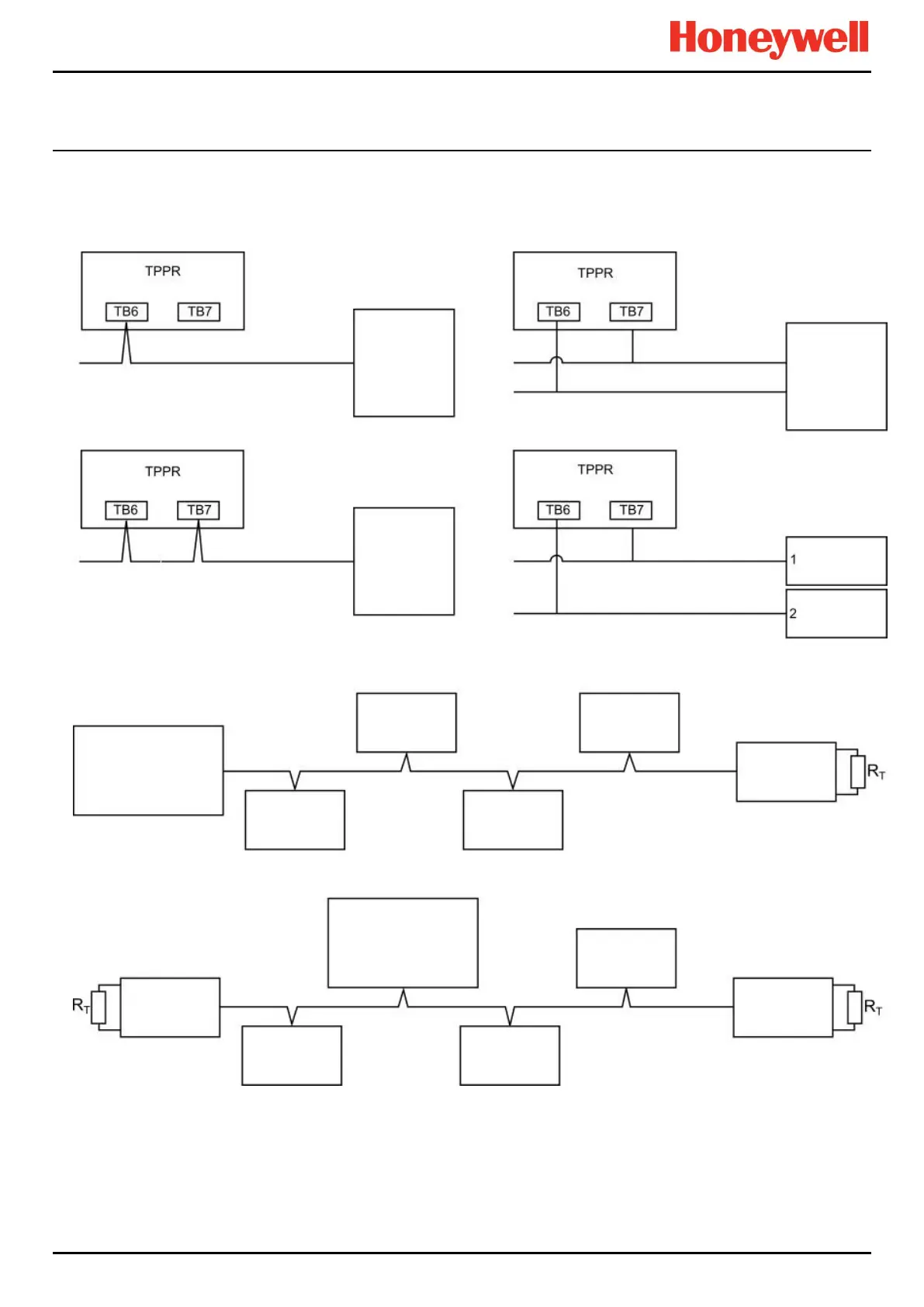
The Modbus interface consists of two independent Modbus ports. The RS485 connections are located on terminals TB6 and
TB7 of the Control Module. For convenience, IN and OUT terminals are provided which are connected together internally.
The diagrams on the next page show example configurations of which the second and third offer redundancy.
Figure 68. Six Modbus Configuration Options
Note: TPPR can fill any of the slave nodes but cannot have same slave IDs in daisy chain or multi-drop configuration.
Note: if a different resistance is required, leave the Modbus Master 120 Ω Jumper pins un-shorted and connect the resistor
directly between TB6 and / or TB7 terminals 3 and 4 (A OUT and B OUT).
Modbus
Master
Modbus
Master
Modbus
Master
Modbus
Modbus
(120 Ω Jumper pins
shorted)
(120 Ω Jumper pins
unshorted)
Node
Node
Node
Node
Node
Node
Node
Node
Node
Node

 Loading...


