EasyManua.ls Logo

Honeywell touchpoint Pro - Table 10. AIM MV Connection Table

Honeywell touchpoint Pro
200 pages
To Next Page IconTo Next Page
To Previous Page IconTo Previous Page
Loading...
MODBUS INSTALLATION
Part. No. 2400M2501_6 Touchpoint Pro
42 Technical Handbook
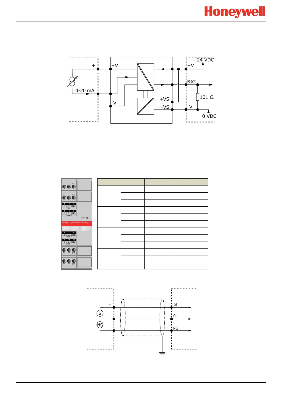
Figure 53. Two Wire Device with an Isolated Barrier
5.2.15 Connecting to an Analogue Input Module mV Bridge
The Analogue Input Module mV Bridge (AIM mV) accepts Catalytic (180 mA to 360 mA reactive bead) type sensors
connected via the module’s front-face terminals.
Bead current is programmable in the range 180mA to 360mA (default 200mA). Bead current may be independently set for
each channel.
Channel
Terminal
Label
Field Device
Input 1
1
S
Sensitive (+)
2
01
Signal
3
NS
Non-sensitive ()
Input 2
4
S
Sensitive (+)
5
01
Signal
6
NS
Non-sensitive ()
Input 3
7
S
Sensitive (+)
8
01
Signal
9
NS
Non-sensitive ()
Input 4
10
S
Sensitive (+)
11
01
Signal
12
NS
Non-sensitive ()
Table 10. AIM mV Connection Table
Figure 54. mV Bridge Catalytic Detector
Device
TPPR
Barrier
Device
TPPR

Table of Contents

Other manuals for Honeywell touchpoint Pro

Related product manuals