INTRODUCTION
Part. No. 2400M2501_6 Touchpoint Pro
12 Technical Handbook
3.2 TPPR Control System Layout
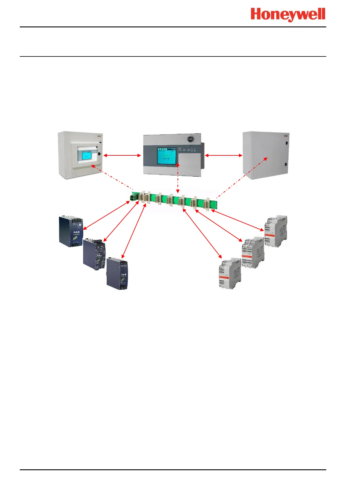
The TPPR Control system can be built from just four main building blocks:
1. One Controller module with colour LCD touch screen User Interface
2. One backplane power and communications rail ( per enclosure or rack)
3. Power Supply modules (AC/DC, DC-UPS, Redundancy, Backup Battery)
4. Plug-in Input / Output (I/O) modules (mV, mA, AIM, DIM, ROM, Modbus)
Figure 16. TPPR Building Blocks
The illustration above shows wall mounted units but rack mounted and floor standing units use the same building blocks.
Enclosures can also hold multiple backplanes to allow for future system expansion.
24 VDC Power Supply
(120/240/480 W)
Relay Output Modules
(ROM)
mV/mA Analogue Input Modules
(AIM)
Digital Input Modules
(DIM)

 Loading...


