POTENTIAL OPERATING ISSUES
Part. No. 2400M2501_6 Touchpoint Pro
160 Technical Handbook
19.3.5 Ring Faults on Commissioned Systems
On Commissioned systems the CCB will attempt to identify the approximate location of a ring break, and will attempt to
identify the modules either side of the break.
If the system cannot communicate with a module by either the A ring or the B ring, the module and its channels will be
shown as faulty. A large number of fault messages may be reported if several modules are affected.
If the Location message merely says ‘Ring A Fault’ or ‘Ring B Fault’, remove any un-initialised modules and recheck the
events log before starting fault diagnosis.
Ring faults on a commissioned system may be the result of recent system changes, disturbance, or damage so:
Review the Active Events screen for information.
Review the System Setup screen and check for unexpected module states.
To help locate ring breaks visually check the power and ring LEDs as described for Ring Faults on Initial
Commissioning.
Visually check any empty backplane slots to ensure that they were not damaged during previous work, then test from
the named faulty module towards the CCB (i.e. reverse the circuit arrows shown in the figures).
Check that modules and connectors are correctly fitted and that all screw terminals are correctly tightened.
Note: The fault message term ‘before’ is relative to the communication Ring A / Ring B direction as shown in the figures.
19.3.6 Spurious Fault Reporting
Due to external factors some reported faults may be spurious, variable or unstable, typically showing high numbers of faults
that are difficult to locate or diagnose. E.g. if a short or open circuit occurs in a remote location the communication ring may
appear to operate normally or ring operation and fault reporting may be intermittent and transient. These faults can be
difficult to diagnose, especially if a cable has degraded over time and/or where moisture ingress may be a factor.
If in doubt:
Check if the occurrences correspond to ambient conditions such as rain, high humidity or dew point.
Check the connections and wiring at remote cabinets and cable joints, and then work backwards toward the Controller
while checking for degraded, damaged or shorted wiring, particularly within exposed cable runs.
19.4 Ring Fault Diagnostics and Debugging Techniques
Key to Figures:
A = Ring A Circuit
B = Ring B Circuit
CCB = Control Central Board
RCM = Ring Coupling Module
M1 etc. = Modules. (Configured Modules may have local or descriptive IDs that are not shown here.)
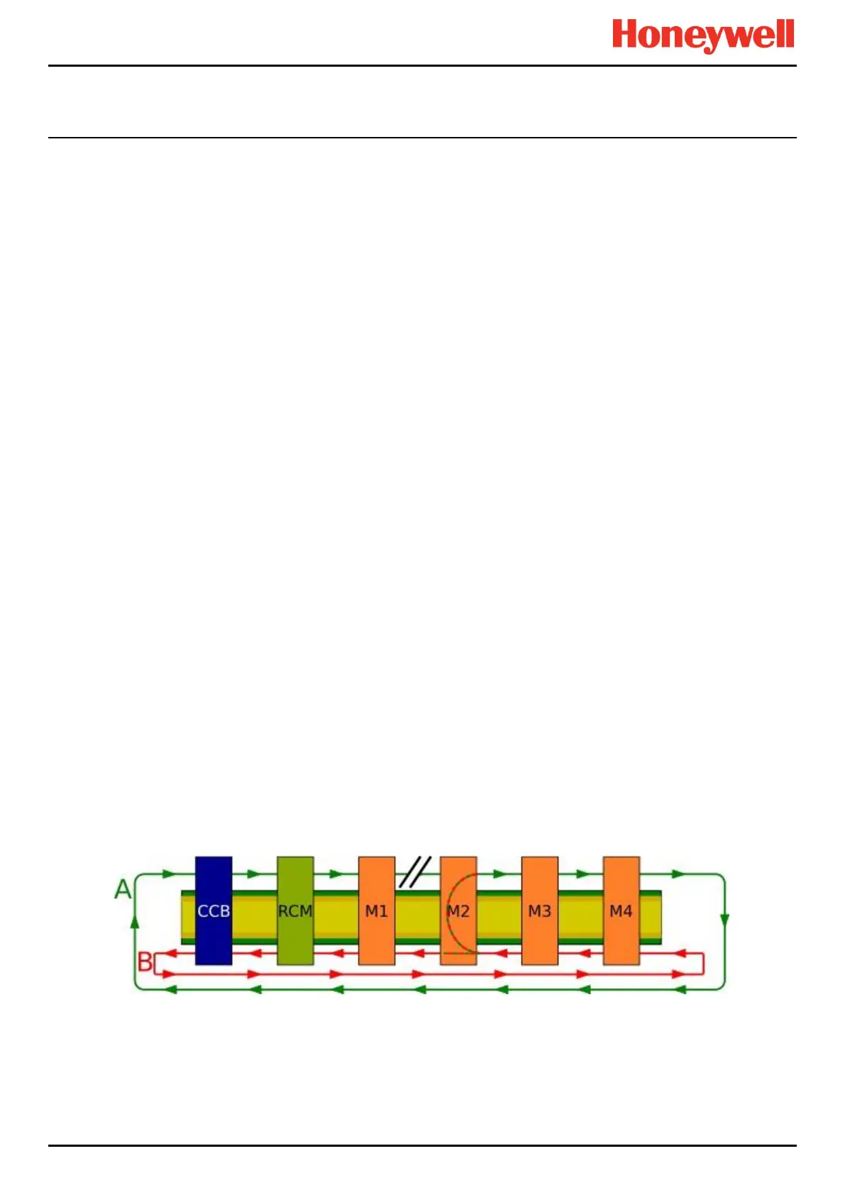
19.4.1 Ring Fault Type 1
Figure 98. Ring Fault Type 1
Rationale:
If a Ring A connection is faulty (e.g. between M1 A-out and M2 A-in) then Module 2 will not receive a signal from ‘A-in’ so
this module will loop back the data from Ring B onto Ring A. The CCB will register that Module 2 has looped the data back
and will tell the UI to show a fault message for ‘Ring A : Module 2’.
Investigation:
Check the Ring A circuit before the named module (e.g. M1 to M2 in this example).
 Loading...


