MODBUS INSTALLATION
Part. No. 2400M2501_6 Touchpoint Pro
48 Technical Handbook
5.3.2 TPPR Controller' System State Relays
The System State Relay connections are located on the Controller at TB4 and TB5 (See Figure 56). They are rated at 30
VDC (3 Amp) or 250 VAC (3 Amp).
5.3.3 Power Supply Unit (PSU) Status Inputs
System Failure Relay (TB4)
Table 15. System State Relay Connections
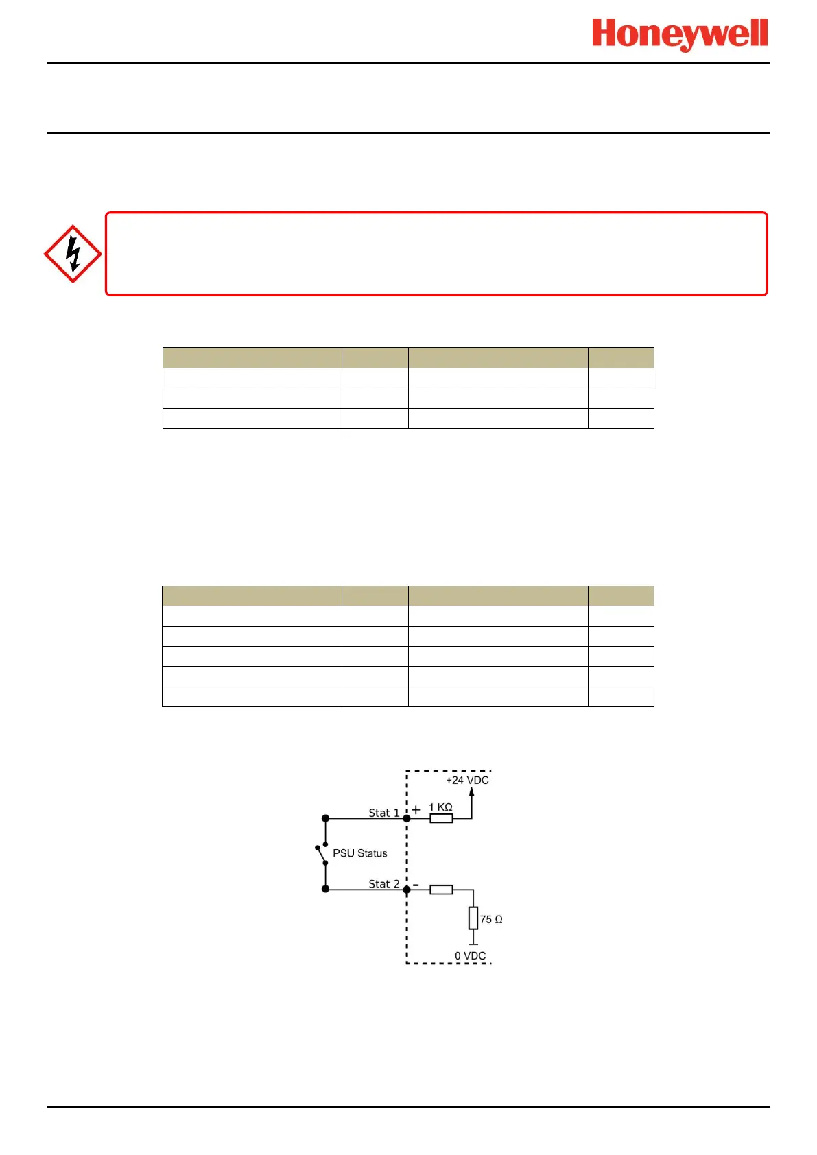
The Power Supply Unit (PSU) Status Input connections are located on the Controller at TB8 and TB9 (see Figure 59).
Four digital inputs are provided on TB8 and TB9. The inputs are provided for PSU status monitoring or ventilation
monitoring. Refer to section 13.16 for further information.
They may be used as general purpose digital inputs if not required for this specialist monitoring.
These inputs can be configured to act as Global Acknowledge, Global Reset or Global Inhibit.
Table 16. PSU Input Connections
Figure 63. PSU Status Circuit
5.3.4 RS485 (Modbus) Interface 1 & 2 Connections
See Ch.6 Modbus Installation for details on installing and connecting to the optional Modbus PCB.
The RS485 Interface functions on TB6 and TB7 are described in the Modbus section. Refer to Chapter 11
An overcurrent protection device should be used if the System State Relays are being used to switch AC voltages.

 Loading...


