MODBUS INSTALLATION
Part. No. 2400M2501_6 Touchpoint Pro
49 Technical Handbook
5.4 First Time Switch On
Before applying power to TPPR, ensure that all wiring and connections are correct and that all glands are tightened.
Switch on the battery isolator switch (if DC-UPS is fitted) and then the main isolator switch.
During the start-up, verify that the front panel LEDs illuminate in sequence and that the buzzer sounds. Verify that the LCD
functions correctly.
During TPPR start-up check that the DC supply voltage is between 18 and 32 VDC at the Vaux terminals of a Relay Output
Module (preferably furthest from the power source) or at the V+ and V- terminals of an Analogue Input Module.
TPPR initialisation typically lasts for 3 – 10 minutes depending on the number of channels and sensors in the system.
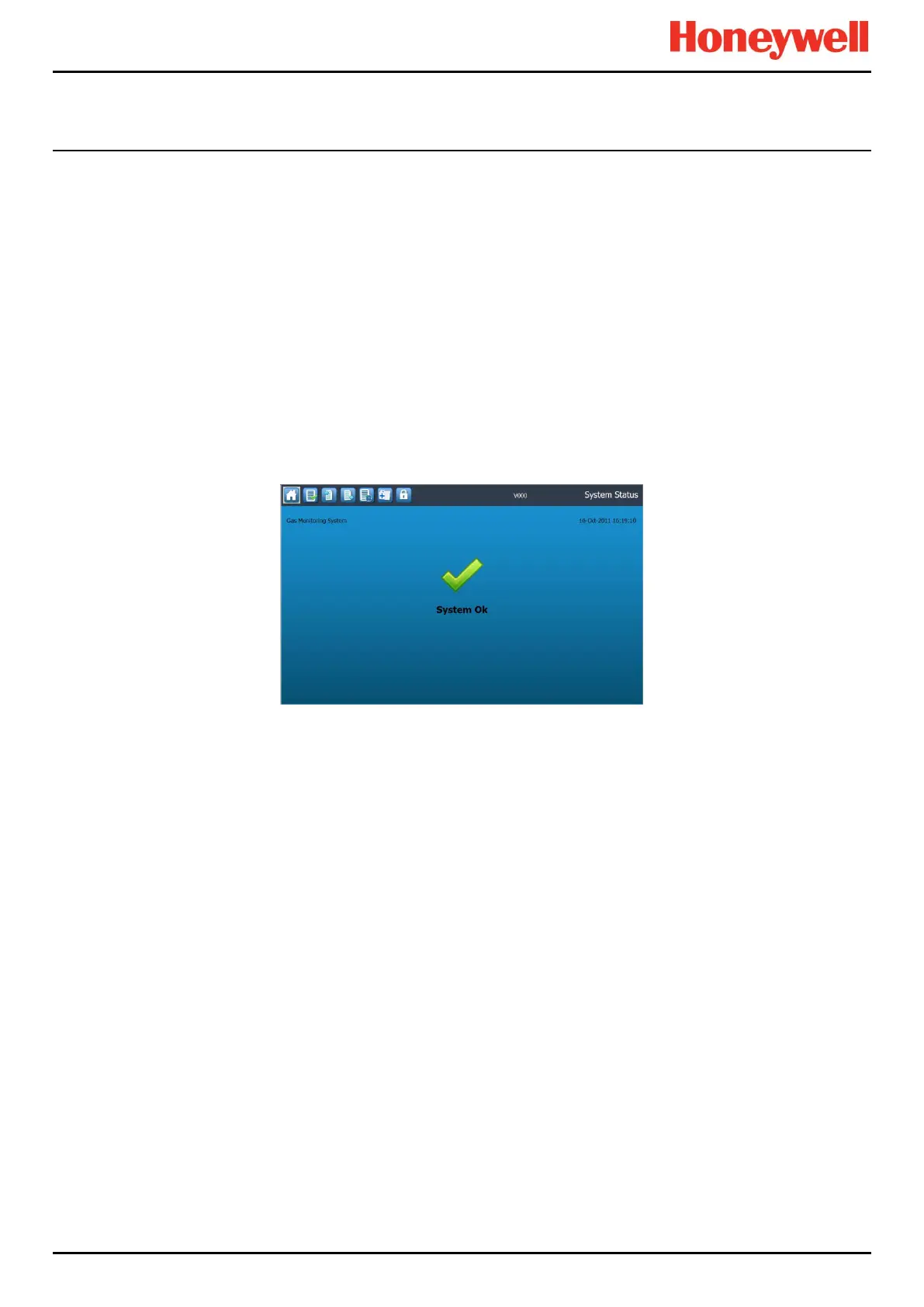
TPPR will then display the System Status screen, indicating the current status of the system.
Note: AIM-mV Bridge channels will be in Inhibit mode until calibrated. In addition, some mA or mV channels may have a
‘power-up’ delay programmed, which means that those channels could remain inhibited until the end of the delay, i.e. up to
5-mins.
The TPPR Controller System Status Screen is shown below.
Figure 64. System Status Screen

 Loading...


